


5
Unpacking
When unpacking please ensure that the following have been removed from the packaging:
Thermal cycler
Power cable
The user is advised to keep the original packaging in case the instrument ever needs to be returned
for service or repair. Omega Engineering, Inc. accepts no responsibility for damage incurred unless
the unit is correctly packed and transported in its original packaging.
Please note that the screen of the thermal cycler is easily damaged by sharp objects such as pens,
pencils and fingernails. This type of damage will be considered as misuse and invalidate the
guarantee for this component.
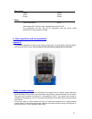
Installation
The instrument should be carried using both hands. Never move or carry the instrument when in use
or connected to the power electricity supply.
1. All Omega Engineering, Inc. instruments are supplied with a power cable; this may be
integral or plug-in.
2. Before connecting the instrument to the power electricity supply, check the voltage against
the rating plate (located on the back of the unit). Ensure that the voltage selector switch
(located above the On/Off switch) is set to the appropriate voltage for the local supply.
Please note that the unit must be grounded to ensure proper electrical safety. Connect the
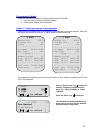
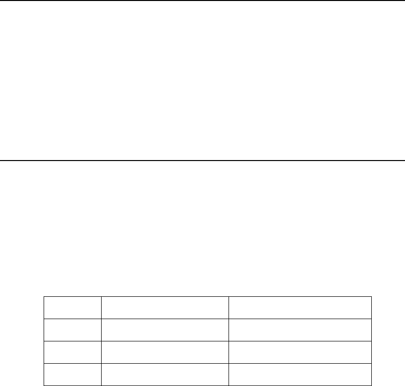
power cable to a suitable plug according to the table below.
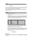
Connection 220/240V, 50/60Hz Supply 110V/120V Supply, 50/60Hz
Live Brown Black
Neutral Blue White
Earth Green/yellow Green
3. Units showing 230V, 50/60Hz on the rating plate also operate between 210 and 260V;
units with 120V, 50/60Hz also operate between 100 and 130V and units marked with
100V will operate between 90 and 110V. In all cases the heating rate will degrade by
approximately 8% at the extremes of the voltage range.
4. Plug the power cable into the socket on the back of the instrument.
5. Place the unit on a suitable flat bench or in a fume cupboard if required, ensuring that the
air inlet vents on the underside are free from obstruction. Position the instrument with a
minimum distance all round of 200mm from walls or other items and between each unit if
multiple units are being used to permit efficient air flow for each instrument.
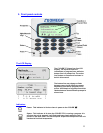
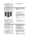
6. Switch on the instrument:
I Power Switch On
O Power Switch Off
Replacement cable
Should the power lead need replacement, a cable of 1mm
2
of harmonized code H05VV-F
connected to an IEC320 plug should be used. IF IN DOUBT CONSULT A QUALIFIED
ELECTRICIAN.