


14
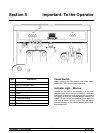
Important: To the Operator
Model 632
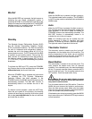
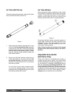
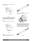
Air Tube (Soft Serve)
The air tube s erves two purposes. One end of the tube
has a hole and the other end does not.
Figure 1
1. After priming the machine, lubricate the o- rings
on the air tube (the end with the hole) and place
it into the mix inlet hole. Every time the draw
handle is raised, new mix and air from the hopper
will flow down into the freezing cylinder. This will
keep the freezing cylinder properly loaded and
will maintain overrun.
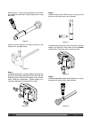
2. During long “No Sale” periods, remove the air
orifice. Lubricate the o- r ings on th e air tube (the
end without the hole), and place it into the mix
inlet hole. This will prevent any mix from entering
the freezing c ylinder.
The a ir orific e is used to meter a certain amount
of air into the freezing cylinder. The air orifice
maintains overrun andallows enough mix toenter
the freezing c ylinder after a draw.
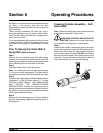
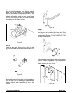
Air Tube (Shake)
Afte r priming the machine, install the air tube. Install
the air tube in the position that will allow for the hole
marked“1” to b ein the downposit ion. This isthe AUT O
position, and will allow mix and air to travel to the
freezing c ylinder while product i s being dis pensed.
Figure 2
During long “No Sale” periods, rev erse the position of
the air tube. Position the air tube to allow the hole
marked “2” to be in the down position. This is the
STANDBY position, and will prevent any m ix from
entering the freezing cylinder.
Note: Be sure to place the air tubes in the correct
position when returning the freezer to the AUTO
position.
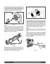
Adjustable Draw Handle
(Soft Serve Only)
These units feature an adjustable draw handle to
provide the best portion control. The draw handle
should be adjusted to provide a flow rate of 5 to 7- 1/2
oz. of product per 10 seconds. To INCREASE the flow
rate, turn the screw COUNTERCLOCKW ISE. Turn
the screw CLOCKWISE to DECREASE the flow rate.
During Sanitizing and Rinsing, the flow rate can be
increased by removing the pivot pin and placing the
restr ictive bar on the TOP. When drawing p roduct,
always place the restrictiv e bar on the bottom.