


18
Operat ing Procedu res
Model 632
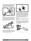
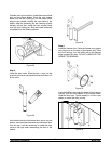
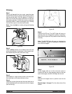
Slide the fork over the bar in the slot of the draw valve.
Secure with pivot pin.
Figure 14
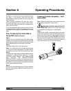
Note: These units feature adjustable draw handles to
provide thebest portion control. The draw handles can
be adjusted for different flow rates. See page 14 for
more information on adjusting these handles.
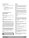
Step 7
Snap the design cap over the end of the door spout.
Figure 15
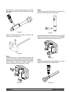
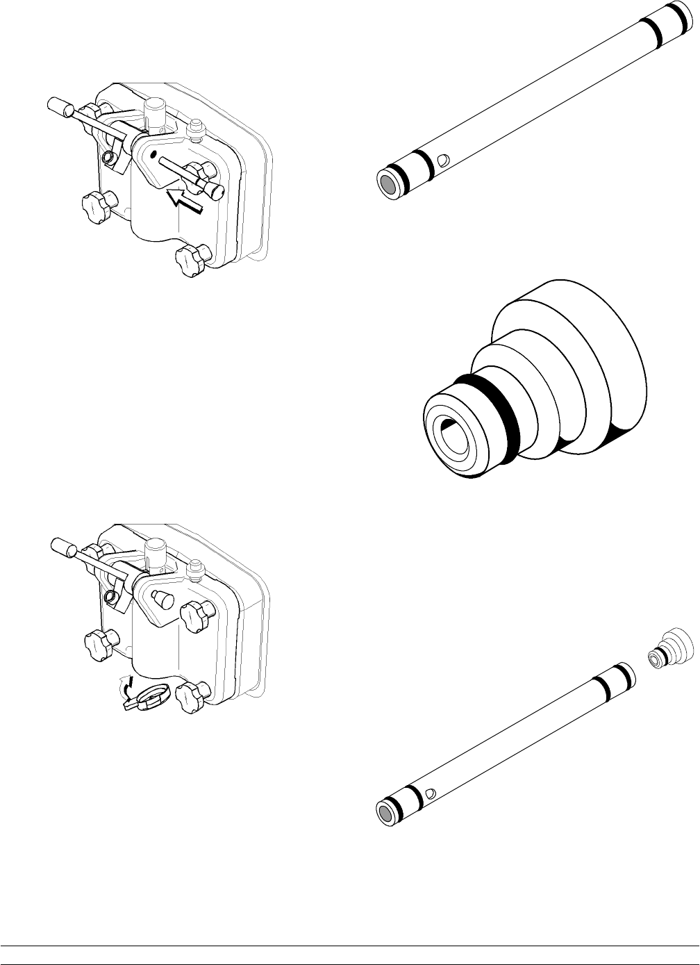
Step 8
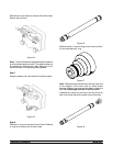
Slide two o- rings on one end of the air tube. Slide two
o- rings on the o ther end of the air tube.
Figure 16
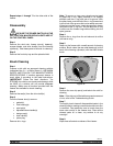
Slide the small o- r ing into the groove of the air orifice.
Do not lubricate the o- ring.
Figure 17
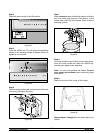
Note: Makesure the hole in theair orificeis clean and
is not clogged. If the hole i n the air orifice s hould
become clogged, use soap and hot water to c lear the
hole. Do not enlarge the hole in the air orifice.
Install the air orifi ce into the hole in the top of the air
tube (in the end without the s mall hole on the side).
Figure 18