


General Data
UNT-PRC001-EN 17
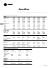
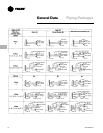
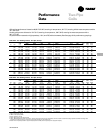
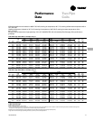
Table GD-1. Modulating Valve Selections for Horizontal Concealed Units
Horizontal Concealed (High Static Motor)
Unit Coil Coil Valve
Size Coil GPM (L/s) WPD (kPa) Cv Cv
2-Row 1.29 (0.08) 8.8 (26.3) 0.66 0.7
02 3-Row 1.80 (0.11) 23.9 (71.3) 0.56 0.7
4-Row 1.84 (0.12) 6.1 (18.3) 1.13 1.5
2-Row 1.58 (0.10) 14.1 (42.2) 0.64 0.7
03 3-Row 1.86 (0.12) 5.4 (16.1) 1.22 1.5
4-Row 2.26 (0.14) 9.7 (28.9) 1.10 1.5
2-Row 1.90 (0.12) 4.6 (13.7) 1.35 1.5
04 3-Row 2.94 (0.19) 13.9 (41.5) 1.20 1.5
4-Row 3.35 (0.21) 22.3 (66.7) 1.08 0.7
2-Row 3.32 (0.21) 15.3 (45.6) 1.29 1.5
06 3-Row 4.24 (0.27) 7.5 (22.3) 2.35 2.5
4-Row 4.99 (0.31) 11.9 (35.6) 2.20 2.5
2-Row 3.90 (0.25) 5.7 (16.9) 2.48 2.5
08 3-Row 5.13 (0.32) 11.8 (35.2) 2.27 2.5
4-Row 5.68 (0.36) 16.9 (50.6) 2.10 2.5
2-Row 5.23 (0.33) 10.8 (32.2) 2.42 2.5
10 3-Row 7.14 (0.45) 24.2 (72.3) 2.21 2.5
4-Row 7.63 (0.48) 32.8 (98.1) 2.03 2.5
2-Row 6.35 (0.40) 16.6 (49.5) 2.37 2.5
12 3-Row 7.98 (0.50) 18.5 (55.3) 2.82 2.5
4-Row 9.47 (0.60) 25.2 (75.4) 2.87 2.5
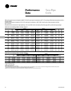
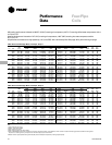
Table GD-2. Modulating Valve Selections for Vertical Cabinet Units
Vertical Cabinet (Free Discharge Motor)
Unit Coil Coil Valve
Size Coil GPM (L/s) WPD (kPa) Cv Cv
2-Row 1.04 (.07) 6.1 (18.2) 0.64 0.7
02 3-Row 1.40 (.09) 15.4 (46.0) 0.54 0.7
4-Row 1.40 (.09) 3.7 (11.1) 1.11 1.5
2-Row 1.32 (.08) 10.3 (30.7) 0.63 0.7
03 3-Row 1.57 (.10) 4.0 (11.8) 1.19 1.5
4-Row 1.88 (.12) 7.0 (20.8) 1.08 0.7
2-Row 1.68 (.11) 3.7 (11.0) 1.33 1.5
04 3-Row 2.25 (.14) 8.6 (25.8) 1.17 1.5
4-Row 2.54 (.16) 13.6 (40.7) 1.05 0.7
2-Row 2.86 (.18) 11.7 (34.9) 1.27 1.5
06 3-Row 3.19 (.20) 4.4 (13.1) 2.31 2.5
4-Row 3.74 (.24) 7.0 (20.9) 2.15 2.5
2-Row 3.14 (.20) 3.8 (11.3) 2.45 2.5
08 3-Row 4.01 (.25) 7.5 (22.3) 2.23 2.5
4-Row 4.44 (.28) 10.8 (32.2) 2.05 2.5
2-Row 4.39 (.28) 7.8 (23.2) 2.39 2.5
10 3-Row 5.60 (.35) 15.4 (46.1) 2.17 2.5
4-Row 5.88 (.37) 20.4 (61.0) 1.98 1.5
2-Row 5.28 (.33) 11.8 (35.1) 2.34 2.5
12 3-Row 6.14 (.39) 11.2 (33.6) 2.79 2.5
4-Row 7.23 (.46) 15.4 (46.0) 2.80 2.5
Selecting the Correct
Modulating Valve Size
Modulating valves are available in any of
four port sizes. These four port sizes
relate to a Cv of 0.7, 1.5, 2.5 or 4.0, which
is the coefficient of flow. The coefficient of
flow is defined as the volume of water
flow through a control valve in the fully
open position with a 1 psig (6.895 kPa)
differential across the valve. It is calcu-
lated using the following formula:
Cv = Q/Square root ∆P
where:
Cv = flow coefficient
Q = flow rate (GPM)
∆P = pressure drop across the valve or
coil (psig).
For good control, the valve Cv should be
approximately equal to the Cv of the
water coil.
Modulating Valve Selection Example
Assume a size 06 fan-coil is selected to
operate at the following conditions:
Vertical Cabinet Fan-Coil
Entering water temperature = 45 F (7 C)
Leaving water temperature = 55 F (13 C)
EAT conditions = 80/67.
The coil is selected as a four-row coil.
Select the best modulating valve size for
this unit.
1
Find the ∆P across the water coil. Refer to
the ARI performance table to determine
the ∆P across the water coil (or use
TOPSS™ selection program). The water
pressure drop is found to be 7.0’ (20.9
kPa) of water at a flow rate of 3.74 gpm.
This converts to a pressure drop of 3.03
psig (1.0 feet of water = 0.4328 psig.)
2
Calculate the Cv of the water coil.
Cv = GPM/Square root ∆P.
Cv = 3.74/Square root 3.03
Cv = 2.15
Therefore, the valve with the Cv of 2.5
should be selected since it has the Cv
which is closest to the Cv of the water
coil. The following tables illustrate
possible valve selections at ARI condi-
tions for horizontal concealed units with a
high static motor and vertical cabinet
units with a free discharge motor.
Note: Do not use these tables for any
applications other than vertical cabinet or
horizontal concealed units at ARI condi-
tions.