Mechanical
Specifications
UNT-PRC001-EN 59
body from piping. Use some means, such
as a pump and chiller bypass, to ensure
the maximum closed off DP rating of the
two-way valves is not exceeded.
Three-Way, Two-Position Control Valves
Normally open three-way, two-position
valves are rated for a maximum 25 psig
(207 kPa) pressure differential across the
valves. Normally closed three-way two-
position valves are rated for a maximum
pressure differential across the valves of
15 psig (103 kPa). A bypass line is piped
on all three-way piping packages with a
balance fitting to set flow through the
bypass line. The balance fitting has a
maximum working pressure of 150 psig
(1,034 kPa). The valves are also available
with a maximum close-off pressure of 50
psig (345 kPa). The valve actuator is easily
removable for service without removing
the valve body from piping.
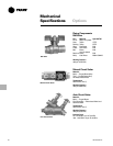
Modulating Control Valves
Two-way and three-way modulating
valves are rated for a maximum pressure
differential across the valves of 50 psig
(345 kPa). The modulating valves are
available in Cv values of 0.7, 1.5, 2.5 and
4.0.
All two-position and modulating control
valves have a maximum working
pressure of 300 psig (2,069 kPa). The
maximum entering water temperature of
the valve is 200 F (93 C).
Electric Heat Coil
The auxiliary electric heating coil is
provided as either the total source of heat
or auxiliary intermediate season heating.
The electric heat coils are located in the
preheat position, and are the open-wire
type. The coils are a nickel chromium
element design. The electric heat oper-
ates at the same voltage as the unit, and
only a single power connection is
necessary.
All standard electric heat coils are UL
listed and interlocked with the fan motor
switch. Therefore, electric heat operation
is possible only when the fan is running. A
transformer is supplied on any voltage
unit, eliminating the need for field
installation of a step-down transformer. A
unit-mounted magnetic contactor is
supplied on all voltages. A high tempera-
ture cutout with automatic reset is
provided as an integral part of the
elements to de-energize the electric heat
in the event of an overheat condition.
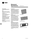
Filters
Filters are concealed from sight and
easily removable. Filters are located
behind an integral access door on
horizontal type units. Filters are either 1”
(25 mm) throwaway or 1”(25 mm)
pleated media throwaway. Pleated media
filters are Farr 30/30.
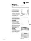
Fresh Air Damper
A fresh air opening with a damper is a
factory-installed option. Dampers are
constructed of 18-gauge steel. Fresh air is
sealed off with gasket material when the
damper is set in the closed position.
Return and fresh air mixes when the
damper is open.
• Manual Damper
The manual damper is field-adjust able to
allow zero to 100 percent fresh air. The
automatic two-position damper is
accompanied by a factory-installed and
wired two-position (spring-return)
actuator.
• Auto Two-Position Damper
The auto two-position damper is factory
set at 25 percent when open. The damper
can be set in the field to allow from zero
to 50 percent fresh air.
• Economizer Damper
The economizer damper is accompanied
by a factory-installed and wired modulat-
ing actuator. The damper is factory set at
25 percent default minimum and 100
percent maximum opening. The damper
is field adjustable using Tracer Summit
®
or Rover™ to allow from zero to 100
percent fresh air


