


Performance
Data
UNT-PRC001-EN 23
Four-Pipe
Coils
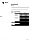
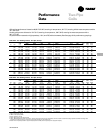
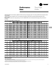
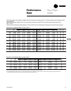
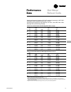
Table PD-10. Free Discharge Motor, Four-Pipe, Group 3
Cooling Heating
CFM TMBH SMBH GPM WPD TMBH GPM WPD 115V 230V 277V
FC Coil (L/s) (TkW) (SkW) (L/s) (kPa) (TkW) Q/ITD (L/s) (kPa) Watt Watt Watt
2 2C1H 188 (89) 4.7 (1.4) 3.5 (1.0) 0.97 (0.06) 5.4 (16.2) 7.6 (2.2) .07 0.51 (0.03) 0.6 (1.9) 60 95 65
2C2H 177 (84) 4.5 (1.3) 3.4 (1.0) 0.93 (0.06) 5.1 (15.1) 12.7 (3.7) .12 0.85 (0.05) 3.2 (9.7) 60 95 65
3C1H 177 (84) 6.3 (1.8) 4.3 (1.3) 1.29 (0.08) 13.4 (40.1) 7.3 (2.1) .07 0.48 (0.03) 0.6 (1.8) 60 95 65
3 2C1H 260 (123) 6.1 (1.8) 4.5 (1.3) 1.28 (0.08) 9.8 (29.2) 10.4 (3.1) .09 0.69 (0.04) 1.3 (3.8) 85 89 101
2C2H 242 (114) 5.9 (1.7) 4.3 (1.3) 1.23 (0.08) 9.1 (27.2) 17.2 (5.1) .16 1.15 (0.07) 6.2 (18.6) 85 89 101
3C1H 242 (114) 6.9 (2.0) 5.1 (1.5) 1.45 (0.09) 3.4 (10.2) 9.9 (2.9) .09 0.66 (0.04) 1.2 (3.4) 85 89 101
4 2C1H 320 (151) 7.7 (2.2) 6.0 (1.8) 1.60 (0.10) 3.4 (10.1) 13.5 (4.0) .12 0.90 (0.06) 2.3 (7.0) 100 107 106
2C2H 304 (144) 7.4 (2.2) 5.8 (1.7) 1.55 (0.10) 3.2 (9.5) 21.4 (6.3) .19 1.43 (0.09) 2.3 (6.9) 100 107 106
3C1H 304 (144) 10.3 (3.0) 7.2 (2.1) 2.12 (0.13) 7.7 (23.1) 13.1 (3.8) .12 0.87 (0.05) 2.2 (6.6) 100 107 106
6 2C1H 508 (240) 13.4 (3.9) 9.9 (2.9) 2.76 (0.17) 11.0 (32.8) 21.6 (6.3) .20 1.44 (0.09) 6.9 (20.6) 125 130 124
2C2H 483 (228) 13.0 (3.8) 9.6 (2.8) 2.68 (0.17) 10.4 (31.1) 34.3 (10.0) .31 2.28 (0.14) 6.5 (19.4) 125 130 124
3C1H 483 (228) 14.4 (4.2) 10.7 (3.1) 2.97 (0.19) 3.8 (11.5) 20.8 (6.1) .19 1.39 (0.09) 6.5 (19.4) 125 130 124
8 2C1H 623 (294) 14.1 (4.1) 11.3 (3.3) 2.90 (0.18) 3.2 (9.7) 27.2 (8.0) .25 1.81 (0.11) 12.5 (37.5) 120 123 133
2C2H 596 (282) 13.7 (4.0) 11.0 (3.2) 2.81 (0.18) 3.1 (9.2) 41.6 (12.2) .38 2.77 (0.17) 2.7 (8.1) 120 123 133
3C1H 596 (282) 18.6 (5.5) 13.1 (3.8) 3.80 (0.24) 6.8 (20.2) 26.4 (7.7) .24 1.76 (0.11) 11.9 (35.5) 120 123 133
10 2C1H 835 (394) 20.6 (6.0) 15.8 (4.6) 4.27 (0.27) 7.4 (22.1) 36.2 (10.6) .33 2.41 (0.15) 25.2 (75.3) 225 237 230
2C2H 796 (376) 20.0 (5.9) 15.2 (4.5) 4.15 (0.26) 7.0 (20.9) 55.8 (16.3) .51 3.72 (0.23) 5.2 (15.4) 225 237 230
3C1H 796 (376) 25.6 (7.5) 17.8 (5.2) 5.28 (0.33) 13.9 (41.4) 35.1 (10.3) .32 2.34 (0.15) 23.8 (71.0) 225 237 230
12 2C1H 923 (436) 24.6 (7.2) 18.1 (5.3) 5.06 (0.32) 10.9 (32.5) 41.1 (12.0) .37 2.74 (0.17) 35.9 (107.2) 220 230 239
2C2H 876 (413) 23.8 (7.0) 17.5 (5.1) 4.91 (0.31) 10.3 (30.7) 63.0 (18.5) .57 4.20 (0.26) 6.9 (20.6) 220 230 239
3C1H 876 (413) 28.1 (8.2) 19.8 (5.8) 5.76 (0.36) 10.0 (29.7) 39.6 (11.6) .36 2.64 (0.17) 33.6 (100.4) 220 230 239
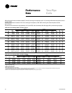
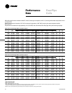
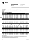
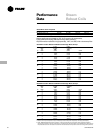
Table PD-11. Free Discharge Motor, Four-Pipe, Group 4
Cooling Heating
CFM TMBH SMBH GPM WPD TMBH GPM WPD 115V
FC Coil (L/s) (TkW) (SkW) (L/s) (kPa) (TkW) Q/ITD (L/s) (kPa) Watt
3 2C1H 270 (128) 6.3 (1.9) 5.0 (1.5) 1.26 (0.08) 2.2 (6.6) 12.0 (3.5) .11 0.80 (0.05) 1.9 (5.7) 86
2C2H 250 (118) 5.9 (1.7) 4.7 (1.4) 1.18 (0.07) 2.0 (5.8) 18.3 (5.4) .17 1.22 (0.08) 1.7 (5.1) 86
3C1H 250 (118) 7.3 (2.1) 5.1 (1.5) 1.46 (0.09) 4.0 (11.9) 11.3 (3.3) .10 0.75 (0.05) 1.7 (5.1) 86
4 2C1H 350 (165) 10.0 (2.9) 7.1 (2.1) 1.99 (0.13) 6.1 (18.2) 16.3 (4.8) .15 1.09 (0.07) 4.2 (12.6) 98
2C2H 320 (151) 9.2 (2.7) 6.5 (2.0) 1.83 (0.12) 5.2 (15.7) 24.4 (7.2) .22 1.63 (0.10) 3.5 (10.5) 98
3C1H 320 (151) 8.9 (2.6) 6.6 (1.9) 1.79 (0.11) 1.5 (4.5) 15.1 (4.4) .14 1.01 (0.06) 3.7 (11.1) 98
6 2C1H 570 (270) 12.6 (3.7) 10.3 (3.0) 2.52 (0.16) 2.5 (7.5) 25.6 (7.5) .23 1.70 (0.11) 11.2 (33.5) 105
2C2H 530 (250) 11.7 (3.4) 9.6 (2.8) 2.35 (0.22) 2.2 (6.6) 37.9 (11.1) .34 2.53 (0.160) 2.3 (6.8) 105
3C1H 530 (250) 15.3 (4.5) 10.8 (3.2) 3.07 (0.19) 4.5 (13.6) 24.2 (7.1) .22 1.61 (0.10) 10.2 (30.5) 105
Note:
1. Medium and low speed capacities are approximately 80 percent and 60 percent respectively of the high speed capacity.
2. Q/ITD = MBH (kW)/(Entering water temperature - Entering air temperature) when ∆T and GPM (L/s) remain constant. To determine heating capacities at a different entering water
temperature or entering air temperature, compute the new ITD and multiply it by the Q/ITD shown.
ARI cooling performance is based on 80/67 F (27/19 C) entering air temperature, 45 F (7 C) entering chilled water temperature with
a 10 F (5.5 C) DT.
Heating performance is based on 70 F (21 C) entering air temperature, 180 F (82 C) entering hot water temperature with a
30 F (17 C) DT.
All performance measured on high speed tap, 115 V, zero ESP, with a throwaway filter. See page 18 for performance groupings.