


Selection
Procedure
UNT-PRC001-EN 65
Model Number Description
Following is a complete description of the basic series fan-coil model number. Each digit
in the model number has a corresponding alphanumeric code to identify the specific
option.
FC X C 04 B 1 L A0 A F 0 1
1 5 10 15
Digits 1, 2 — Unit Type
FC = Fan-coil
Digit 3 — Model
X = Exposed fan
P = With plenum
R = With ceiling access panel, ship
separate
Digit 4 — Development Sequence “C”
Digits 5, 6 — Unit Size
04
06
08
Digit 7 — Coil
B = 3 row cooling/heating
C = 4 row cooling/heating
D = 2 row cooling/1 row heating
E = 2 row cooling/2 row heating
F = 3 row cooling/1 row heating
L = 3 row cooling; aux. electric heat
M = 4 row cooling; aux. electric heat
Digit 8 — Unit Voltage
1 = 115/60/1
2 = 208/60/1
4 = 230/60/1
5 = 110-120/50/1
6 = 220-240/50/1
Digit 9 — Piping Connections
L = Left hand connections
R = Right hand connections
Digits 10, 11 — Design Sequence
“A0”
Digit 12 — Motor
A = Free discharge
B = High static
Digit 13 — Control
0 = None
F = Fan speed switch
Digit 14 — Auxilliary Electric Heat
0 = None
A = 1.0 kW (.75 kW at 208V)
B = 1.5 kW (1.1 kW at 208V)
C = 2.0 kW (1.5 kW at 208V)
D = 2.5 kW (1.9 kW at 208V)
E = 3.0 kW (2.2 kW at 208V)
F = 4.0 kW (3.0 kW at 208V)
G = 5.0 kW (3.8 kW at 208V)
H = 6.0 kW (4.4 kW at 208V)
Digit 15 — End Valve
0 = None
1 = Ball valve
Digit 16 — Main Control Valve
(Line Voltage Only)
0 = None
A = 2 way, 2 pos. NO
B = 3 way, 2 pos. NO
C = 2 way, 2 pos. NC
D = 3 way, 2 pos. NC
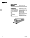
Basic Series
Model Number