


Electrical Data
70
UNT-PRC001-EN
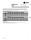
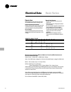
Table B-ED-1. Electric Heat kW
Unit Size Unit Voltage kW kW kW kW kW kW kW kW
04 115 1.0 1.5 2.0 2.5
230 1.0 1.5 2.0 2.5
208 0.75 1.1 1.5 1.9
06 115 2.0 3.0
230 2.0 3.0 4.0 5.0
208 1.5 2.2 3.0 3.8
08 115 2.0 3.0
230 2.0 3.0 4.0 5.0 6.0
208 1.5 2.2 3.0 3.8 4.4
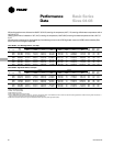
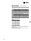
Minimum Circuit Ampacity (MCA) and Maximum Fuse Size (MFS) Calculations for
Fan-Coils with Electric Heat:
Heater Amps = (Heater kW x 1000)/Heater Voltage
Note: Use 120V heater voltage for 115V units. Use 240V heater voltage for 230V units.
MCA = 1.25 x (heater amps + all motor FLA’s)
MFS or HACR Type Circuit Breaker =
(2.25 x Largest Motor FLA) + Second Motor FLA + Heater Amps
HACR (Heating, Air-Conditioning and Refrigeration) type circuit breakers are required
in the branch circuit wiring for all fan-coils with electric heat. See the Electrical Data
section for motor FLA’s.
Note: Select a standard fuse size or HACR type circuit breaker equal to the MCA.
Use the next larger standard size if the MCA does not equal a standard size. Standard
fuse sizes are: 15, 20, 25, 30, 35, 40, 45, 50, and 60 amps
Fan-coil electric heat MBH = (heater kW) (3.413)
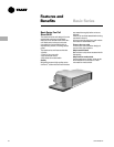
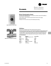
Electric Heat
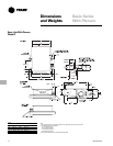
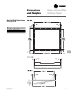
Basic series fan-coils with inlet plenums
are available with electric heating coils.
Coil Construction and Location
Electric heat coils are open wire type with
a nickel chrominum element design. All
coils are located in the preheat position.
Power Supply
Units have single-point power since the
electric heating elements operate on line
voltage.
Electric Heat Features
• All basic series fan-coil units are UL
approved.
• Units require only a single-point electri-
cal connection.
• A unit mounted magnetic contactor(s) is
(are) supplied on all unit voltages.
• A high temperature cutout with auto-
matic reset de-energizes the electric
heat in the event of an overheat
condition.
• When hydronic heating is active, a
lockout sensor will disable the electric
heat.
Basic Series