


Performance
Data
UNT-PRC001-EN 25
Hot Water
Reheat Coils
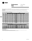
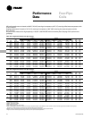
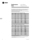
The following performance data represents the 1-row hot water and steam reheat coils
that are available on fan-coil units in conjunction with a 2, 3 or 4-row cooling coil.
Heating performance is based on 70 F (21 C) entering air temperature, 180 F (82 C)
entering hot water temperature with a 20 F (-7 C) DT.
All performance measured on high speed tap, 115 V, zero ESP, with a throwaway filter.
See page 18 for performance groupings.
Table PD-14. Hot Water Reheat Coil With Free Discharge Motor, Group 1
Main
Coil TMBH GPM WPD
FC Rows (TkW) Q/ITD (L/s) (Pa)
2 2.9 (.8) 0.03 0.3 (.02) 0.01 (30)
02 3 2.8 (.8) 0.03 0.3 (.02) 0.01 (30)
4 2.7 (.8) 0.02 0.3 (.02) 0.01 (30)
2 4.1 (1.2) 0.04 0.4 (.03) 0.02 (60)
03 3 4.0 (1.2) 0.04 0.4 (.03) 0.02 (60)
4 3.8 (1.1) 0.04 0.4 (.03) 0.02 (60)
2 5.6 (1.6) 0.05 0.6 (.04) 0.04 (120)
04 3 5.6 (1.6) 0.05 0.6 (.04) 0.04 (120)
4 5.3 (1.6) 0.05 0.5 (.03) 0.03 (90)
2 9.3 (2.7) 0.09 0.9 (.06) 0.10 (299)
06 3 9.3 (2.7) 0.09 0.9 (.06) 0.10 (299)
4 8.9 (2.6) 0.08 0.9 (.06) 0.09 (269)
2 12.5 (3.7) 0.11 1.2 (.08) 0.18 (538)
08 3 11.9 (3.5) 0.11 1.2 (.08) 0.17 (508)
4 11.4 (3.3) 0.10 1.1 (.07) 0.16 (478)
2 16.1 (4.7) 0.15 1.6 (.10) 0.32 (957)
10 3 16.2 (4.7) 0.15 1.6 (.10) 0.32 (957)
4 15.6 (4.6) 0.14 1.6 (.10) 0.30 (897)
2 18.8 (5.5) 0.17 1.9 (.12) 0.45 (1350)
12 3 18.5 (5.4) 0.17 1.8 (.11) 0.44 (1320)
4 17.8 (5.2) 0.16 1.8 (.11) 0.40 (1200)
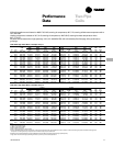
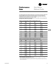
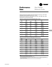
Table PD-15. Hot Water Reheat Coil With Free Discharge Motor, Group 2
Main
Coil TMBH GPM WPD
FC Rows (TkW) Q/ITD (L/s) (Pa)
2 2.7 (.8) 0.03 0.3 (.02) 0.01 (30)
02 3 2.6 (.8) 0.02 0.3 (.02) 0.01 (30)
4 2.5 (.7) 0.02 0.3 (.02) 0.01 (30)
2 3.8 (1.1) 0.03 0.4 (.03) 0.02 (60)
03 3 3.7 (1.1) 0.03 0.4 (.03) 0.02 (60)
4 3.6 (1.1) 0.03 0.4 (.03) 0.02 (60)
2 5.3 (1.6) 0.05 0.5 (.03) 0.03 (90)
04 3 5.2 (1.5) 0.05 0.5 (.03) 0.03 (90)
4 5.0 (1.5) 0.05 0.5 (.03) 0.03 (90)
2 8.8 (2.6) 0.08 0.9 (.06) 0.09 (269)
06 3 8.7 (2.5) 0.08 0.9 (.06) 0.09 (269)
4 8.5 (2.5) 0.08 0.8 (.05) 0.08 (239)
2 11.7 (3.4) 0.11 1.2 (.08) 0.17 (508)
08 3 11.2 (3.3) 0.10 1.1 (.07) 0.15 (448)
4 10.9 (3.2) 0.10 1.1 (.07) 0.15 (448)
2 15.2 (4.5) 0.14 1.5 (.09) 0.29 (867)
10 3 15.2 (4.5) 0.14 1.5 (.09) 0.29 (867)
4 14.8 (4.3) 0.13 1.5 (.09) 0.27 (807)
2 17.7 (5.2) 0.16 1.8 (.11) 0.40 (1200)
12 3 17.4 (5.1) 0.16 1.7 (.11) 0.39 (1170)
4 16.9 (5.0) 0.15 1.7 (.11) 0.37 (1110)
Note:
1. Medium and low speed capacities are approximately
80 percent and 60 percent respectively of the high speed capacity.
2. Q/ITD = MBH (kW)/(Entering water temperature - Entering air temperature) when ∆T and GPM (L/s) remain constant. To
determine heating capacities at a different entering water temperature or entering air temperature, compute the new ITD and
multiply it by the Q/ITD shown.