


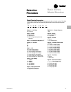
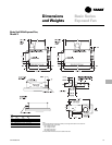
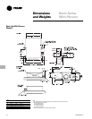
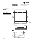


Mechanical
Specifications
UNT-PRC001-EN76
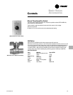
Basic Series Fan-Coil
Mechanical Specifications
Capacity
Unit capacities are certified under
Industry Room Fan-Coil Air Conditioner
Certification Program in accordance with
ARI Standard 440-97.
Safety
All basic series units are UL listed.
Construction
The basic series unit includes a chassis,
coil, fan wheel(s), fan board, and motor.
Units also include a sloped, galvanized
main drain pan. Steel parts exposed to
moisture are galvanized. The chassis
construction is 18-gauge galvanized steel,
and is continuous throughout the unit. The
unit is insulated with closed-cell insulation.
Ceiling Access Panel
The ceiling access panel fabrication is 18-
gauge steel and ships separate from the
unit. Also, the ceiling access panel
includes tamperproof screw fasteners
and a safety chain. Panels are made rigid
by channel forming. All ceiling access
panels are cleaned, bonderized, and
painted with deluxe beige baked powder
finish. Standard finish meets ASTM B117
specifications (salt spray test).
Inlet Plenum
The inlet plenum construction is 18-gauge
galvanized steel. It includes a 1" (25 mm)
throwaway filter.
Fan
The aluminum fan wheels are centrifugal
forward-curved and double-width. Fan
wheels and housings are corrosion
resistant. Fan housings construction is
formed sheet metal.
Motor
The motor has a permanent split capaci-
tor, integral thermal overload protection,
and is permanently lubricated. It is
capable of starting at 78 percent of rated
voltage and operating at 90 percent of
rated voltage on all speed settings. The
motor is run tested in assembled units.
Coil
All water coils are burst tested at 450
psig (3,103 kPA) (air) and leak tested at
100 psig (690 kPa) (air under water).
Maximum main coil working pressure is
300 psig (2,069 kPa). Maximum entering
water temperature is 200 F (93 C). Tubes
and u-bends are
3
/
8
" (10 mm) OD copper.
Fins are aluminum and are mechanically
bonded to the copper tubes. Coil stubouts
are
5
/
8
" (16 mm) OD copper tubing. All
coils include a manual air vent.
Ball Valve
A ball-type stop valve is available for
field-installation on both the entering and
leaving water pipe. The ball valve is a
shutoff valve with a maximum working
pressure of 400 psig (2,758 kPa).
Electric Heat Coil
The auxiliary electric heating coil is
provided as either the total source of
heat or auxiliary intermediate season
heating. The electric heat coils are
located in the preheat position, and are
the open-wire type. The coils are a nickel
chromium element design. The electric
heat operates at the same voltage as the
unit, and only a single power connection
is necessary. All standard electric heat
coils are UL listed. A unit-mounted
magnetic contactor is supplied on all
voltages. A high temperature cutout with
automatic reset is provided as an integral
part of the elements to de-energize the
electric heat in the event of an overheat
condition.
Basic Series