


Mechanical
Specifications
UNT-PRC001-EN58
UniTrane
®
Fan-Coil
Mechanical Specifications
Performance Data
Capacity: Unit capacities are certified
under Industry Room Fan-Coil Air
Conditioner Certification Program in
accordance with ARI Standard 440-97.
Safety: All standard units are UL listed in
the United States and Canada and
comply with NFPA 90A requirements.
Construction
All Units
The unit includes a chassis, coil(s), fan
wheel(s), fan casing(s), fan board and
motor(s). Units also include a noncorro-
sive, ABS main drain pan, positively
sloped in every plane and insulated with
closed-cell insulation. Horizontal units
and all units with standard piping
packages also include a thermoplastic
auxiliary drain pan. Steel parts exposed to
moisture are galvanized. The fan board
assembly and both drain pans are easily
removable. The fan board assembly
includes a quick-disconnect motor plug.
The chassis construction is 18-gauge
galvanized steel, and continuous
throughout the unit. The unit is acousti-
cally and thermally insulated with closed-
cell insulation. All panels are made rigid
by channel forming.
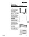
Vertical Cabinet and Slope Top Units
Front panel fabrication is 16-gauge
galvanized steel. All other panels are 18-
gauge galvanized steel. The discharge
grille is recessed to resist condensate
formation. Hinged access door construc-
tion is 20-gauge steel and is flush with
top panel.
Horizontal Cabinet Units
All panels are 18-gauge galvanized steel,
including the bottom panel. Discharge
grille is recessed to resist condensate
formation. The hinged access door is flush
with front panel. Bottom panels ship with
tamperproof screw fasteners and a
safety chain.
Concealed/Recessed Units
Exposed panels on recessed units are 18-
gauge steel construction and ship
separate from the unit. Bottom panels on
horizontal recessed models ship stan-
dard with tamperproof screw fasteners
and a safety chain.
Low Vertical Unit
Front panels are of 16-gauge galvanized
steel. All cabinet parts are made rigid by
channel forming. End panel is removable
for piping access. Hinged access door
construction is 20-gauge steel and flush
with top panel.
Unit Finish
All cabinet parts and exposed recessed
panels are cleaned, bonderized, phos-
phatized, and painted with a baked
powder finish available in six decorator
colors. Standard finish meets ASTM
B117 specifications (salt spray test).
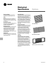
Fans
The aluminum fan wheels are centrifugal
forward-curved and double-width. Fan
wheels and housings are corrosion
resistant. Fan housing construction is
formed sheet metal. Low vertical units
utilize a tangential wheel design.
Motors
All permanent split capacitor motors are
run tested in assembled units. All motors
have integral thermal overload protection
with a maximum ambient operating
temperature of 104 F and are perma-
nently lubricated. Motors are capable of
starting at 78 percent of rated voltage and
operating at 90 percent of rated voltage
on all speed settings. Motors can operate
up to 10 percent over voltage.
Coils
All water coils are burst tested at 450 psig
(3,103 kPa) (air) and leak tested at 100
psig (690 kPa) (air under water).
Maximum main coil working pressure is
300 psig (2,069 kPa). Maximum entering
water temperature is 200 F
(93 C). Tubes and u-bends are
3
/
8
”
(10 mm) OD copper. Fins are aluminum
and are mechanically bonded to the
copper tubes. Coil stubouts are
5
/
8
”
(16 mm) OD copper tubing.
Reheat Coils
Reheat coils are available for use with
both hot water and steam. Hot water
maximum working pressure is 300 psig
(2,069 kPa), and the maximum entering
water temperature is 200 F (93 C). The
steam coil maximum working pressure is
15 psig (103 kPa). The reheat coils are
constructed of single circuit
5
/
8
”(16 mm)
copper tubes with aluminum fins. Piping
connections are expanded to accept
standard copper tubing
5
/
8
” (16 mm) OD.
Piping Packages
All piping packages are burst tested at
450 psig (3,103 kPa) (air) and leak tested
at 100 psig (690 kPa) (air under water).
The maximum working pressure of the
interconnecting piping is 300 psig (2,069
kPa).
Piping packages are available in either
basic or deluxe configurations. The
deluxe package includes unions at the
coil connections and a 20 mesh strainer
on the supply side with a pressure rating
on the strainer of up to 400 psig (2,758
kPa). The basic package does not include
either unions or the strainer. A choice of
end valves are available on both the basic
and deluxe piping packages.
Ball Valve Supply and Return
A ball-type stop valve is available on both
the supply and return of the piping
package. The ball valve is a shutoff valve
only with a maximum working pressure
of 400 psig (2,758 kPa).
Ball Valve Supply, Manual Circuit Setter
Return
A ball valve is provided on the supply
with a manual circuit setter on the return.
The manual circuit setter is a combina-
tion flow-setting device and shutoff valve
that includes two Schrader ports. The
maximum working pressure of the valve
is 300 psig (2,069 kPa).
Ball Valve S & R, Auto Circuit Setter
Return
Ball type end valves are mounted on the
supply and return, with an additional
auto circuit setter mounted on the return.
The auto circuit setter is an automatic
flow control valve that is sized to allow a
specific GPM through the coil. Auto
circuit setters also include two P/T plugs
and have a maximum working pressure
of 400 psig (2,758 kPa).
The piping package is designed so that
any condensation is directed into the
UniTrane
®
auxiliary drain pan. Insulation
of piping package is not required.
Two-Way, Two-Position Control Valves
Two-way, two-position valves are rated
for a maximum pressure differential
across the valves of 25 psig (172 kPa).
The valves are also available with a
close-off pressure of 50 psig (345 kPa).
The valve actuator is easily removable
for service without removing the valve