


13
SERVICE
This section provides procedures for testing and
replacing various major components used in this
dispenser should service become necessary. Re-
fer to
Troubleshooting
for assistance in determin-
ing the cause of any problem.
WARNING - Inspection, testing, and repair of electri-
cal equipment should be performed only by quali-
fied service personnel. The dispenser should be
unplugged when servicing, except when electrical
tests are required and the test procedure specifi-
cally states to plug-in the dispenser.
COMPONENT ACCESS
WARNING - Disconnect the dispenser from the power
source before the removal of any panel or the
replacement of any component.
All components are accessible by opening the
door, removal of the door panels, dispenser top
covers, hopper(s), hopper support plate, splash
guard, splash panel w/drip tray, lower front access
panel and rear access cover.
Refer to the contents listing for component loca-
tion.
Contents
Auger Drive Components (FMD-1) ....................... 13
Auger Drive Components (FMD-2) ....................... 15
Ballast ................................................................... 18
Control Thermostat...............................................19
Control Board (FMD-2) ......................................... 20
Dispense Switch ................................................... 22
Fan........................................................................24
Frother ..................................................................25
Hopper Drive Board(FMD-1) ................................. 27
Increase/Decrease Switch (FMD-2) ...................... 28
Lamp Holder .........................................................29
Lamp .................................................................... 29
Lamp Starter and Socket ...................................... 30
Level Control Board and Level Probe (FMD-1) ..... 30
Limit Thermostat .................................................. 32
Rinse/Run Switch (FMD-1) ................................... 32
Rinse/Run Switch (FMD-2) ................................... 33
Solenoid (Cold Water - Optional FMD-2 Only) ...... 34
Solenoid (Dispense) ............................................. 35
Solenoid (Inlet) .....................................................36
Tank Heater...........................................................37
Tank Heater Switch ...............................................38
Transformer (FMD-2)............................................ 39
Whipper Motor ..................................................... 26
Wiring Diagram ...............................................40,41
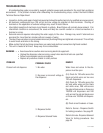
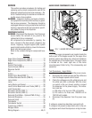
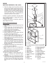
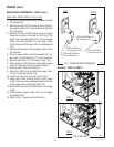
FIG. 1 AUGER DRIVE COMPONENTS
Location
The auger components are located inside the
bottom part of the hopper except for the auger drive
bracket, spacer and retaing clip, which are located on
the outside rear of the hopper base. The auger motor
is located on the lower right rear of the motor
mounting panel. Refer to Fig. 2 for disassembly and
assembly.
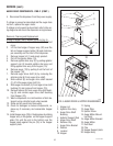
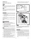
Test Procedures - Auger Motor
1. Disconnect the dispenser from the power source.
2. Disconnect the white/red wire and the white wire
from the hopper speed control board.
3. Check the voltage across the white/red wire and
the white wire with a voltmeter. With the rinse/
run switch in the run (lower) position, connect
the dispenser to the power supply. The indica-
tion must be :
a) 120 volts ac for two wire 120 volt models.
b) 120 volts ac for three wire 120/208 volt or
120/240 volt models.
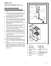
4. Disconnect the dispenser from the power sup-
ply.
If voltage is present as described, proceed to #5.
If voltage is not present as described, refer to the wir-
ing diagram and check the dispenser wiring harness.
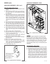
AUGER DRIVE COMPONENTS FMD-1
P1665
J
1
29112 101598