


34
12
11
9
8
7
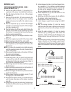
J4
J1
J2
J3
J1
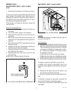
SOLENOID VALVE (COLD WATER
OPTIONAL)(FMD-2 ONLY)
6. Check the solenoid valve for coil action. Connect
the dispenser to the power source. With the cold
jumper plug installed press the left dispense switch
and listen carefully in the vicinity of the solenoid
valve for a “clicking” sound as the magnet attracts.
7. Disconnect the dispenser from the power source.
If the sound is heard as described and water will not
pass through the solenoid valve, there may be a block-
age in the water line before the solenoid valve or, the
solenoid valve may require inspection for wear, and
removal of waterborne particles.
If the sound is not heard as described, replace the
solenoid valve.
Removal and Replacement:
1. Loosen the two screws securing the component
bracket to the dispenser base. Lift the component
bracket off of the base and move to the right.
2. Remove the white and blue from the solenoid
valve.
3. Turn-off the water supply to the dispenser.
4. Disconnect the water lines to and from the sole-
noid valve.
5. Loosen the two #8-32 screws and washers secur-
ing the solenoid mounting bracket to the base.
Remove solenoid bracket and solenoid valve as an
assembly.
6. Remove the two #10-32 screws and lockwashers
securing the solenoid valve to the solenoid bracket.
7. Using two #10-32 screws and lockwashers install
new solenoid valve on solenoid mounting bracket.
8. Install the solenoid valve and bracket on the dis-
penser base and tighten the two #8-32 screws.
9. Securely fasten the water lines to and from the
solenoid valve.
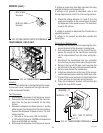
10. Refer to Fig. 35 when reconnecting the wires.
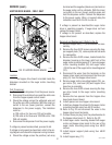
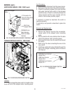
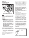
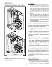
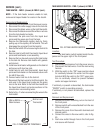
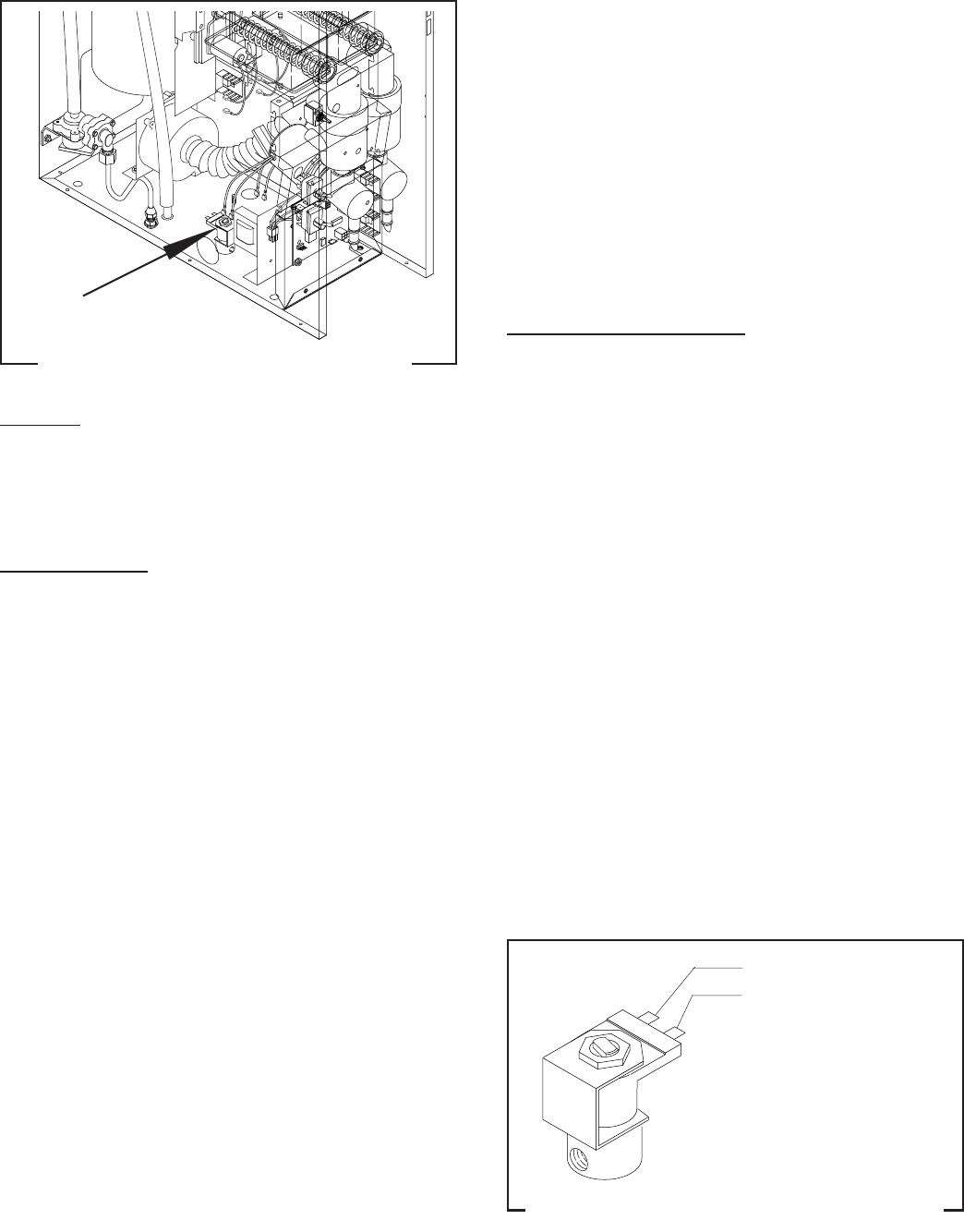
SERVICE (cont.)
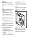
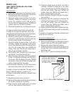
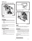
FIG. 34 COLD WATER SOLENOID VALVE
P1666
Location:
The cold water solenoid valve is located on
the left side of the dispenser base just behind the com-
ponent bracket.
Test Procedures:
1. Disconnect the dispenser from the power source.
2. Disconnect the white and blue wires from the
solenoid valve. With the cold jumper plug in-
stalled press the left dispense switch on front of
the door.
3. Check the voltage across the white and blue wires
with a voltmeter. Connect the dispenser to the
power source. The indication must be 120 volts
ac for two wire 120 volt models, three wire 120/
208 and 120/240 volt models.
4. Disconnect the dispenser from the power source.
If voltage is present as described, proceed to #5
If voltage is not present as described, refer to wiring
diagram and check dispenser wiring harness.
5. Check for continuity across the solenoid valve
coil terminals.
If continuity is present as described, reconnect the
white and blue wires to the solenoid.
If continuity is not present as described, replace the
solenoid valve.
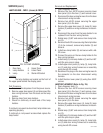
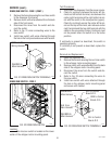
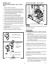
FIG. 35 COLD WATER SOLENOID TERMINALS
P1215
BLU to Main Harness
WHI to Main Wiring
Harness
29112 101598