


20
12
11
9
8
7
J4
J1
J2
J3
J
1
SERVICE (cont.)
a) 120 volts ac for two wire 120 volt models.
b) 208 volts ac for three wire 120/208 volt models.
c) 240 volts ac for three wire 120/240 volt models.
5. Disconnect the dispenser from the power source.
If voltage is present as described the control thermo-
stat is operating properly. Reinstall bulb into the tank.
If voltage is not present as described, replace the
thermostat.
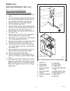
Removal and Replacement.
1. Remove the thermostat capillary bulb by firmly
pulling-up on the capillary at the tank lid. This will
disengage the grommet from the tank lid.
2. Loosen the two #6-32 screws securing the ther-
mostat to the front tank mounting bracket.
3. Disconnect the wires from the thermostat.
4. Remove thermostat and remove the screws and
spacers from the thermostat.
5. Discard thermostat.
6. Install two spacers and two #6-32 screws on the
new thermostat.
7. Position the thermostat on the botttom side of the
front tank mounting bracket and tighten the two
#6-32 screws.
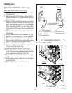
8. Slide the grommet to the line 4.5" above the bulb
on the new capillary tube.
9. Insert the capillary bulb through the hole in the
tank lid and press the grommet firmly and evenly
so that the groove in the grommet fits into the tank
lid.
10. Carefully bend the capillary tube so that the tube
and bulb inside the tank are in the vertical position
and away from any electrical connections.
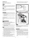
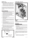
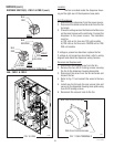
11. Refer to Fig. 11 and reconnect the wires.
NOTE - The capillary tube must be clear of any electri-
cal termination and not kinked.
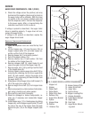
CONTROL THERMOSTAT - FMD-1 & FMD-2 (cont.)
FIG. 11 THERMOSTAT TERMINALS
P1668
BLK from Limit
Thermostat
BLK from Tank
Heater Switch
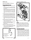
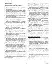
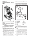
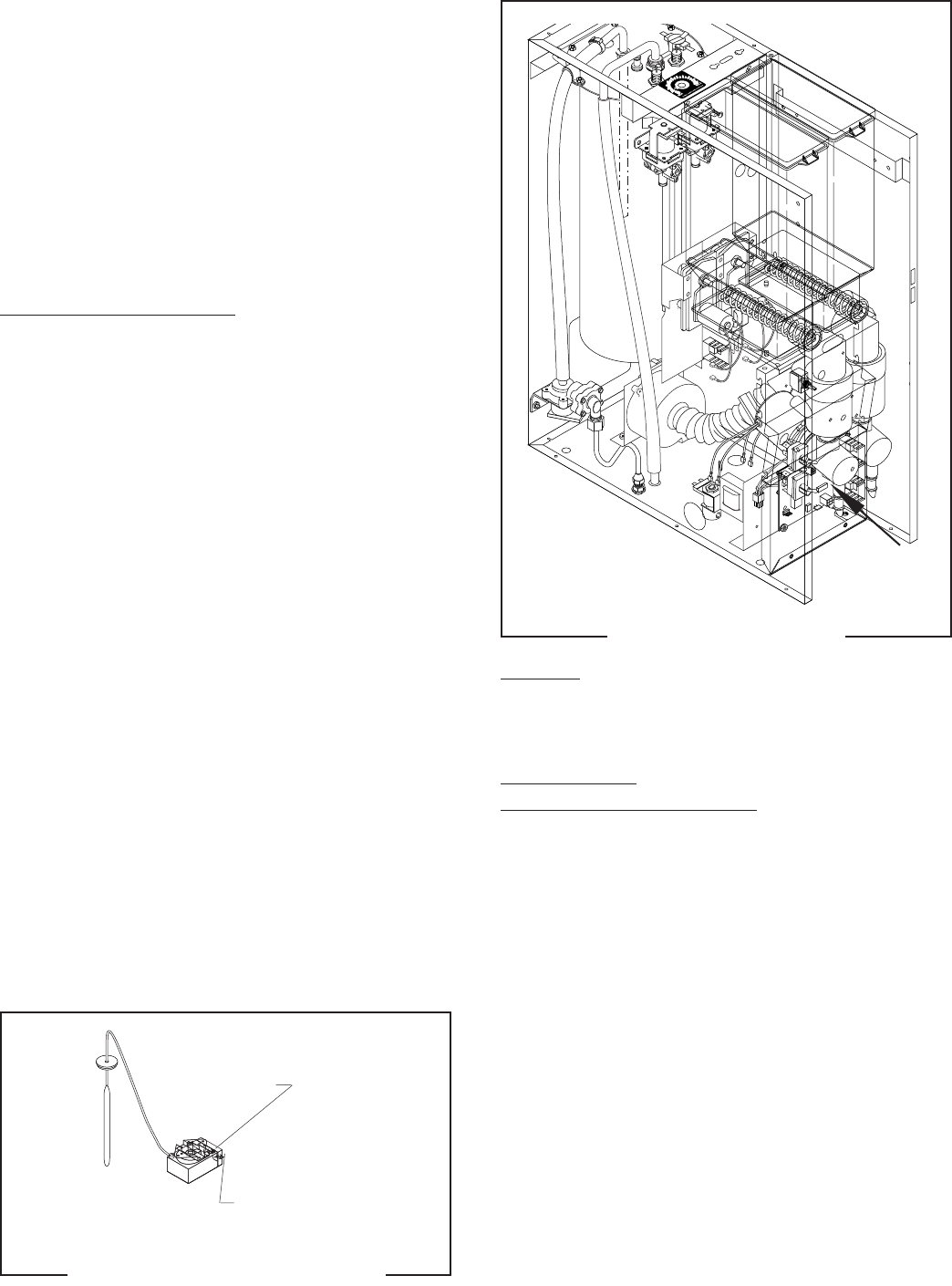
CONTROL BOARD - FMD-2 ONLY
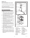
FIG. 12 CONTROL BOARD
Location:
The Control Board is located behind the lower
front access cover mounted on the component bracket.
Test Procedure:
Liquid Level Control Circuitry:
1. Disconnect the dispenser from the power source.
2. Disconnect the six pin connector from J3 of the
control board.
3. Check the voltage across pins 5 & 6 of the six pin
connector on the wiring harness with a voltmeter.
Connect the dispenser to the power source. The
indication must be 24 volts ac.
4. Disconnect the dispenser from the power source.
If voltage is present as described, proceed to step 5.
If voltage is not present as described, refer to the
wiring diagram and check the dispenser wiring har-
ness.
5. Reconnect the six pin connector of the wiring
harness to J3 of the control board.
P1666
29112 101598