


23
SERVICE (cont.)
DISPENSE SWITCH(S) - FMD-1 & FMD-2 (cont.)
Test Procedure:
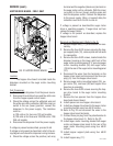
FMD-1
1. Disconnect the dispenser from the power source.
2. Open the dispenser door and remove the bottom
door cover.
3. Disconnect the wires from the door interconnect
wiring harness to the dispense switch.
4. Check for voltage across the black wire and the red
wire from the door interconnect wiring harness.
Connect the dispenser to the power supply. The
indication must be:
a) 120 volts ac for two wire 120 volt models.
b) 120 volts ac for three wire 120/208 volt or 120/
240 volt models.
5. Disconnect the dispenser from the power source.
If voltage is present as described, proceed to #6.
If voltage is not present as described, refer to the wir-
ing diagram and check the dispenser wiring harness.
6. Check for continuity across the terminals with the
switch in the“ON” pressed position. Continuity
must not be present when the switch is in the
“OFF” released position.
If continuity is present as described, reconnect the
connector to the door interconnect wiring harness,
the switch is operating properly.
If continuity is not present as described, replace the
switch.
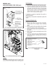
FMD-2
1. Disconnect the dispenser from the power source.
2. Open the dispenser door and remove the bottom
door cover.
3. Disconnect the wires from the door interconnect
wiring harness to the dispense switch to be tested.
4. Check for voltage across the black and red/white
wires for the right dispense switch or the black and
red wires for the left dispense switch from the door
interconnect wiring harness. Connect the dis-
penser to the power supply. The indication must
be:
a) 120 volts ac for two wire 120 volt models.
b) 120 volts ac for three wire 120/208 volt or 120/
240 volt models.
5. Disconnect the dispenser from the power source.
If voltage is present as described, proceed to #6.
If voltage is not present as described, refer to the wir-
ing diagram and check the dispenser wiring harness.
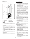
6. With a voltmeter, check the voltage across the
black/white (+) and orange (-) wires for the right
dispense switch, or blue/white (+) and orange (-)
for the left dispense switch from the door intercon-
nect wiring harness. Connect the dispenser to the
power source. The indication must be +5 volts dc.
If voltage is present as described, proceed to #7.
If voltage is not present as described, refer to the
wiring diagram and check the dispenser wiring har-
ness.
7. Check for continuity across the terminals (top
right to top left; bottom right to bottom left) of the
dispense switch with the switch in the “ON” posi-
tion. Continuity must not present when the switch
is in the “OFF” released position.
If continuity is present as described, reconnect the
connector to the door interconnect wiring harness,
the switch is operating properly.
If continuity is not present as described, replace the
switch.
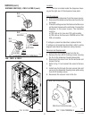
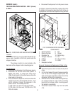
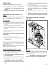
Removal and Replacement
1. Open the dispenser door.
2. Remove the five #6-32 screws securing the bot-
tom door cover and remove cover.
3. Disconnect the wires on the dispense switch from
the door interconnect wiring harness.
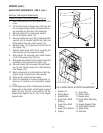
4. Compress the clips inside the door on the dis-
pense switch and gently push the switch through
the opening
5. Push the new switch into the opening and spread
the clips to hold the switch in the door.
6. Reconnect the wires to the dispense switch from
the door interconnect wiring harness.
7. Reinstall the door bottom cover using five #6-32
screws.
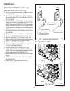
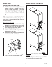
8. Refer to Fig. 15 when reconnecting wires.
29112 101598