


38
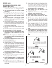
NOTE - If the tank heater remains unable to heat,
remove and inspect heater for cracks in the sheath.
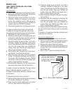
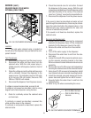
Removal and Replacement:
1. Disconnect the dispenser from the power source.
2. Disconnect the water supply tube on the tank lid.
3. Disconnect the black wires on the limit thermstat.
4. Disconnect the black wire and the white or red wire
from the tank heater terminals.
5. Disconnect the pink wire from the liquid level
probe and the green wire from the tank.
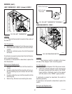
6. Remove the thermostat capillary bulb by firmly
pulling-up on the capillary at the tank lid. This will
disengage the grommet from the tank lid.
7. Remove the ten #8-32 nuts securing the tank lid to
the tank.
8. Remove tank lid with limit thermostat, liquid level
probe and tank heater as an assembly.
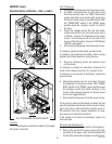
9. Remove the two hex nuts securing the tank heater
to the tank lid. Remove tank heater with gaskets
and discard.
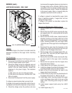
10. Install new tank heater with gaskets on the tank lid
and secure with two hex nuts.
11. Install tank lid with limit thermostat, liquid level
probe and tank heater on the tank and secure with
ten #8-32 hex nuts.
12. Connect water inlet line to the tank lid.
13. Reconnect the black wires to limit thermostat, the
pink wire to the liquid level probe and the green
wire to the tank. Refer to the limit thermostat and
the liquid level board and probe sections in this
manual when reconnecting wires.
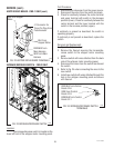
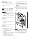
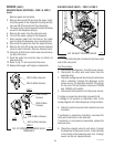
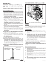
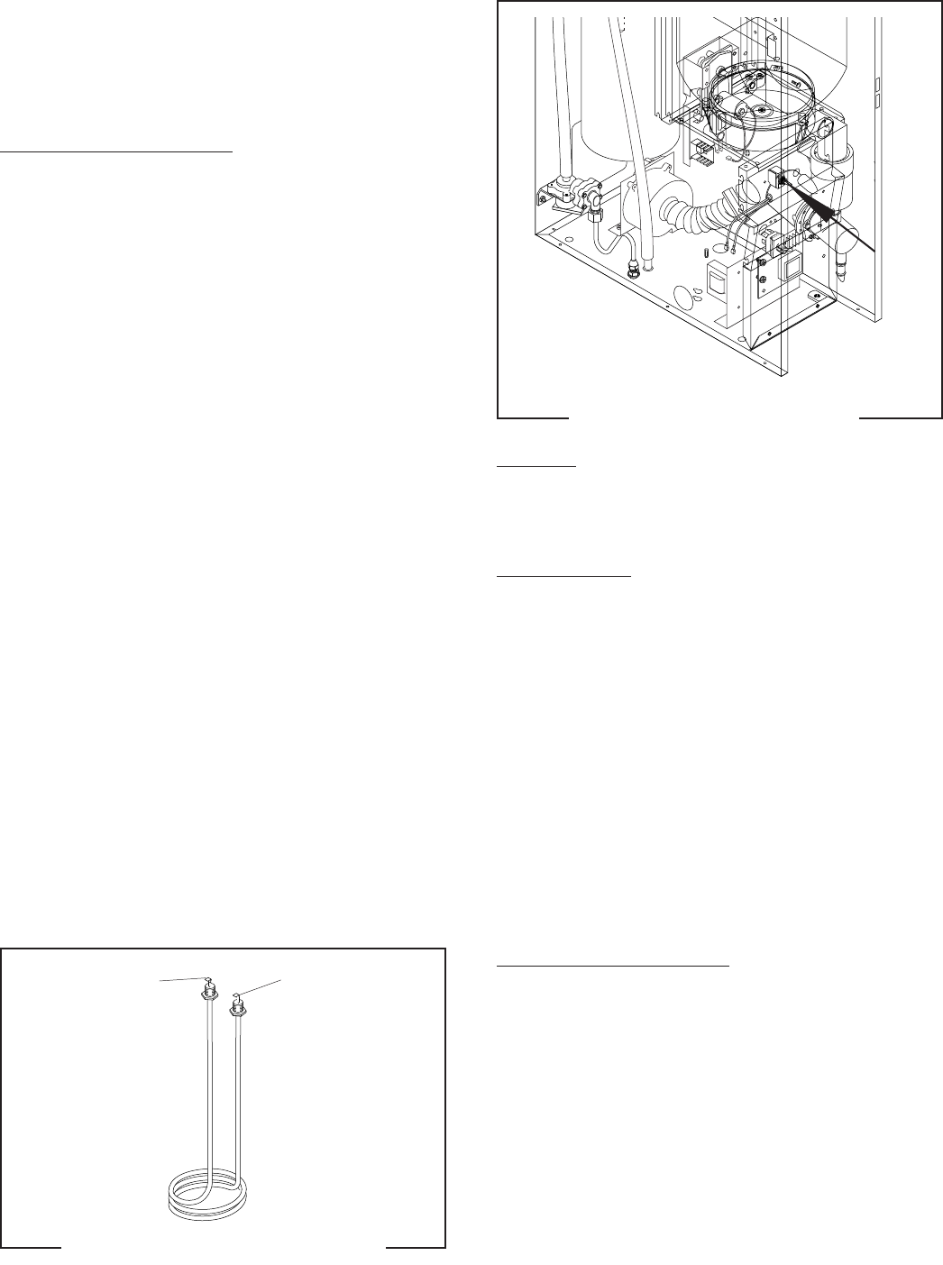
14. Refer to Fig. 41 when reconnecting the wires to the
tank heater.
TANK HEATER - FMD-1 (shown) & FMD-2 (cont.)
SERVICE (cont.)
FIG. 41 TANK HEATER TERMINALS
P1218
WHI or RED to
Main Harness
BLK to Limit
Thermostat
J1
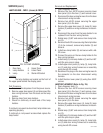
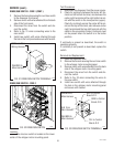
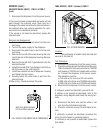
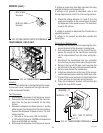
FIG. 42 TANK HEATER SWITCH
TANK HEATER SWITCH - FMD-1 (shown) & FMD-2
P1665
Location:
The tank heater switch located inside the dis-
penser on the upper right of the front panel.
Test Procedure:
1. Disconnect the dispenser from the power source.
2. Disconnect the black wires from the main wiring
harness.
3. With the switch in the “ON” lower position check
for continuity between the center and the upper
terminal. With the switch in the “OFF” upper posi-
tion no continuity should be present between
center and upper terminals.
If continuity is present as described, the tank heater
“ON/OFF” switch is operating properly.
If continuity is not present as described, replace the
switch.
Removal and Replacement:
1. Remove the switch mounting nut on the front of
the front panel.
2. Remove switch with wires attached from the rear
of the front panel.
3. Remove the wires from the switch terminals and
discard switch.
4. Connect the wires to the new switch, refer to Fig.
43.
5. Push new switch through hole in the front panel
and secure with facenut.
29112 101598