


19
J1
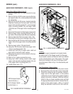
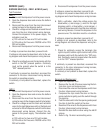
Location
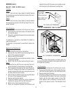
FMD-1
The front door lamp ballast is located behind
the front access panel on the left front side of the com-
ponent bracket.
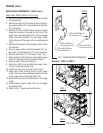
FMD-2
The front door lamp ballast is located behind
the front access panel on the left rear side of the com-
ponent bracket.
Test Procedure
1. Disconnect the dispenser from the power source.
2. Disconnect the two black lead on the ballast from
the main harness.
3. Check for continuity between the two black leads
on the ballast.
If continuity is present as described the ballast is
operating properly.
If continuity is not present as described, replace the
ballast.
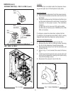
Removal and Replacement
FMD-1
1. Disconnect the wires from the ballast.
2. Remove the two #8-32 screws securing the bal-
last to the component bracket.
3. Remove and discard ballast.
4. Using two #8-32 screws install new ballast on the
component bracket.
5. Refer to the Fig. 9 when reconnecting the wires.
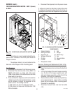
FMD-2
1. Loosen the two #8-32 screws securing the com-
ponent bracket to the dispenser housing base.
2. Pull component bracket out the front of the dis-
penser far enough so the leads on the ballast can
be disconnected from the main wiring harness and
the door interconnect harness.
3. Remove the two #8-32 screws securing the ballast
the rear of the component bracket.
4. Remove and discard ballast.
5. Install new ballast on the rear of the component
bracket and secure with two #8-32 screws.
6. Refer to Fig. 9 and reconnect the wires.
7. Place the component bracket into position and
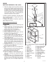
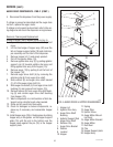
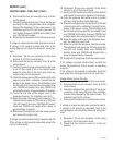
BLK to BLK
from Main
Wiring Harness
BLK to BLU from
Main Harness
P1447
FIG. 9 BALLAST TERMINALS
SERVICE (cont.)
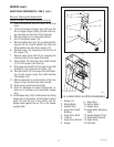
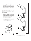
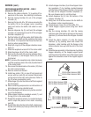
CONTROL THERMOSTAT - FMD-1 & FMD-2
FIG. 10 CONTROL THERMOSTAT
P1665
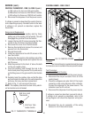
Location
The control thermostat is located under the
front tank mounting bracket on the upper right side of
the dispenser housing.
Test Procedure
1. Disconnect the dispenser from the power source.
2. Disconnect the black wire of the control thermo-
stat from the black lead from the limit thermostat.
3. Remove bulb from the tank.
4. Check the voltage across black wire on the control
thermostat and the white or red wire on the tank
heater with the tank heater switch in the “ON”
lower position with a voltmeter. Connect the dis-
penser to the power source. The indication must
be:
BALLAST - FMD-1 & FMD-2 (cont.)
tighten the two #8-32 screws securing the compo-
nent bracket to the dispenser housing base.
29112 101598