


37
J1
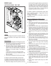
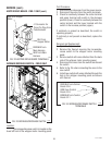
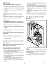
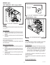
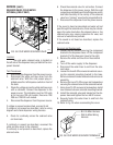
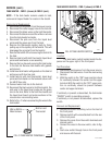
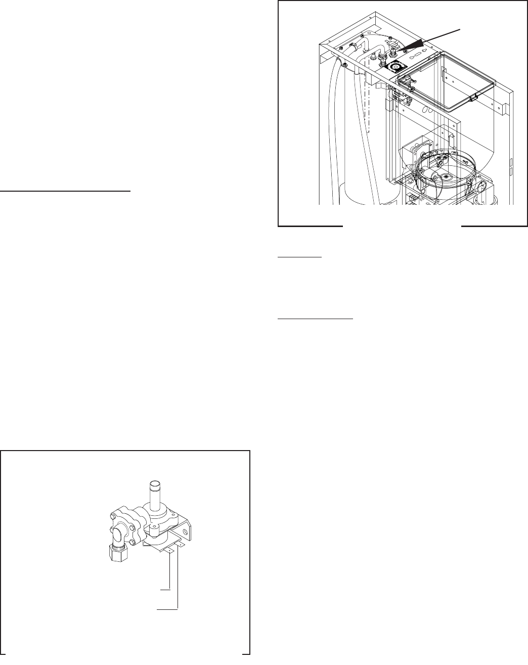
TANK HEATER - FMD-1 (shown) & FMD-2
FIG. 40 TANK HEATER
Location:
The tank heater is located inside the tank and
secured to the tank lid.
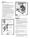
Test Procedure:
1. Disconnect the dispenser from the power source.
2. Check the voltage across the black and white wires
120 volt models or black and red wires for 120/208
volt models or 120/240 volt models with a voltme-
ter. Connect the dispenser to the power source.
The indication must be:
a) 120 volts ac for two wire 120 volt models;
b) 208 volts ac for three wire 120/208 volt models.
c) 240 volts ac for three wire 120/240 volt models.
3. Disconnect the dispenser from the power source.
If voltage is present as described, proceed to #4.
If voltage is not present as described, refer to the
dispenser wiring diagram and check the wiring har-
ness.
4. Disconnect the black wire and the white or red
wire from the tank heater terminals.
5. Check for continuity across the tank heater termi-
nals.
If continuity is present as described, reconnect the
wires, the tank heater is operating properly.
If continuity is not present as described, replace the
tank heater.
P1665
P1217
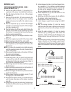
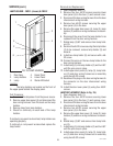
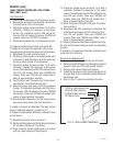
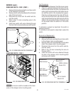
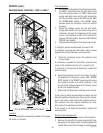
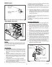
FIG. 39 INLET SOLENOID VALVE TERMINALS
SERVICE (cont.)
SOLENOID VALVE (INLET) - FMD-1 & FMD-2
(cont.)
WHI from Main Harness
7. Disconnect the dispenser from the power source.
If the sound is heard as described and water will not
pass through the solenoid valve, there may be a
blockage in the water line before the solenoid valve or,
the solenoid valve may require inspection for wear,
and removal of waterborne particles.
If the sound is not heard as described, replace the
solenoid valve.
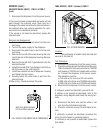
Removal and Replacement:
1. Remove the white and violet wires from the sole-
noid valve.
2. Turn-off the water supply to the dispenser.
3. Disconnect the water lines to and from the sole-
noid valve.
4. Remove the two #8-32 screws securing the sole-
noid to the rear of the dispenser housing. Remove
solenoid.
5. Remove the two #8-32 U-Type fasteners from the
solenoid bracket.
6. Install the two #8-32 U-Type fasteners and the two
#8-32 screws on the new solenoid.
7. Install new solenoid on rear of dispenser housing
and tighten the two screws
8. Securely fasten the water lines to and from the
solenoid valve.
9.Refer to Fig. 39 and reconnect the wires.
VIO from Main Harness
29112 101598