


31
SERVICE (cont.)
Test Procedure:
1. Disconnect the dispenser from the power source.
2. Remove the violet wire from terminal 1 & pink wire
from terminal 4 of the circuit board.
3. Check the voltage across terminals 2 & 3 with a
voltmeter. Connect the dispenser to the power
source. The indication must be 120 volts ac for
two wire 120 volt models, three wire 120/208 volt
models, three wire 120/240 volt models.
4. Disconnect the dispenser from the power source.
If voltage is present as described, proceed to #5.
If voltage is not present as described, refer to the
wiring diagram and check the dispenser wiring haness.
5. Reconnect the violet wire to terminal 1.
6. Carefully connect a piece of insulated jumper wire
to terminal 4. Keep the other end of this wire away
from any metal surface of the dispenser.
7. Check the voltage across terminals 1 & 3 with a
voltmeter. Connect the dispenser to the power
source. The indication must be 120 volts ac for two
wire 120 volt models, three wire 120/208 volt
models, three wire 120/240 volt models after a
delay of approximately 5 seconds.
8. Touch the free end of jumper wire to the compo-
nent bracket. The indication must be 0.
9. Move the jumper wire away from the component
bracket. The indication must again be 120 volts ac
for two wire 120 volt models, three wire 120/208
volt models , three wire 120/240 volt models after
a delay of approximately 5 seconds.
10. Disconnect the dispenser from the power source
and remove the jumper wire from terminal 4.
If voltage is present as described, the level control
board is operating properly, proceed to #11.
If voltage is not present as described, replace the level
control board.
11. Reconnect the pink wire to terminal 4.
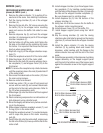
12. Gently pull the probe out of the tank lid and inspect
for corrosion. Replace it if necessary.
13. Place the probe so that neither end is in contact
with any metal surface of the dispenser.
LEVEL CONTROL BOARD AND LEVEL PROBE -
FMD-1 ONLY (cont.)
14. Check the voltage across terminals 1 & 3 with a
voltmeter. Connect the dispenser to the power
source. The indication must be 120 volts ac for two
wire 120 volt models, three wire 120/208 volt
models, three wire 120/240 volt models after a
delay of approximately 5 seconds.
15. Move the probe's flat end to the tank. The indica-
tion must be 0.
16. Move the probe's flat end away from the tank. The
indication should again be 120 volts ac for two
wire 120 volt models, three wire 120/208 volt
models, three wire 120/240 volt models after a
delay of approximately 5 seconds.
If voltage is present as described, reinstall the probe,
the level control board and level probe are operating
properly.
If voltage is not present as described, check the pink
probe wire for continuity.
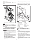
Removal and Replacement:
1. Remove all wires from the level control board.
2. Remove two #8-32 keps nuts holding level control
board to right side of the component bracket.
3. Remove level control board and spacers.
4. Install the new level control board and spacers to
the right side of the component bracket using two
#8-32 keps nuts.
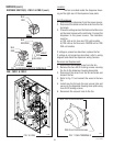
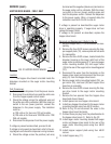
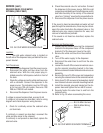
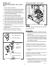
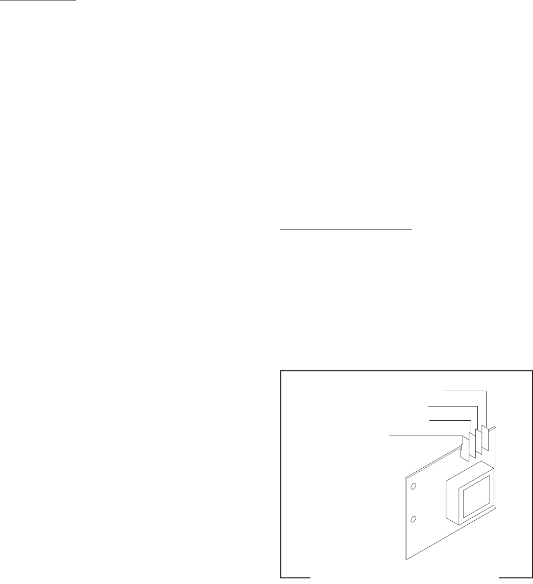
5. Refer to Fig. 27 when reconnecting the wires.
P1671
FIG. 27 LEVEL BOARD TERMINALS
TI VIO to Inlet Solenoid Coil
T2 BLK to Main Harness
T3 WHI to Main Harness
T4 PNK to Probe
29112 101598