


29
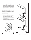
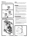
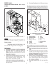
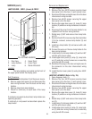
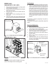
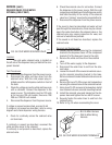
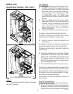
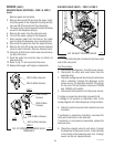
LAMP HOLDER - FMD-1 (shown) & FMD-2
FIG. 25 LAMP HOLDERS
P1670
3
4
6
1. Door Assy
2. Lamp Holders
3. Lamp
4. Upper Panel
5. Lower Panel
6. Starter W/Socket
5
2
1
Location:
The lamp holders are located on the front of
the upper panel behind the display panel.
Test Procedure:
1. Disconnect the dispenser from the power source.
2. Remove upper door panel (4) and disconnect the
door wiring harness from the leads on the lamp
holders.
3. Remove lamp from lamp holders.
4. Check for continuity on each lead of the lamp
holders.
If continuity is present as described, lamp holders are
operating properly.
If continuity is not present as described replace the
lamp holder.
SERVICE (cont.)
Removal and Replacement:
1. Open dispenser door (1).
2. Remove the four #8-32 screws securing lower
door panel (5) to the door (1) and remove cover.
3. Disconnect the door wiring harness from the door
interconnect wiring harness.
4. Remove two #8-32 screws securing the upper
door panel (4) to the door.
5. Remove the upper door cover (4), lamp (3), lamp
holders (2) and door wiring harness as an assem-
bly.
6. Disconnect the wires from the lamp holder to be
replaced from the door wiring harness.
7. Rotate lamp (3) 90° and remove from lamp hold-
ers (2).
8. Remove the #6-32 screw securing the lamp holder
(2) to be removed, remove lamp holder (2) and
discard.
9. Install new lamp holder (2) and secure with a #6-
32 screw.
10. Connect the wires on the new lamp holder to the
door wiring harness.
11. Install lamp (3) into lamp holders (2) and turn 90°
until the pins snap in place.
12. Install upper door panel (4), lamp (3), lamp hold-
ers (2) and door wiring harness as an assembly
using two #8-32 screws.
13. Reconnect the plug on the door wiring harness to
the connector on the door interconnect wiring
harness.
14. Install the door lower panel (5) using four #8-32
screws.
LAMP REPLACEMENT (Refer to Fig. 25)
1. Open dispenser door (1).
2. Remove the four #8-32 screws securing lower
door panel (5) to the door (1) and remove cover.
3. Disconnect the door wiring harness from the door
interconnect wiring harness.
4. Remove two #8-32 screws securing the upper
door panel (4) to the door.
5. Remove the upper door cover (4), lamp (3), lamp
holders (2) and door wiring harness as an assem-
bly.
6. Rotate lamp (3) 90° and remove from lamp hold-
ers (2).
7. Install lamp (3) into lamp holders (2) and turn 90°
until the pins snap in place.
8. Install upper door panel (4), lamp (3), lamp hold-
ers (2) and door wiring harness as an assembly
using two #8-32 screws.
29112 101598