


27
SERVICE (cont.)
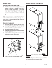
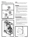
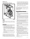
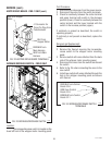
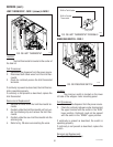
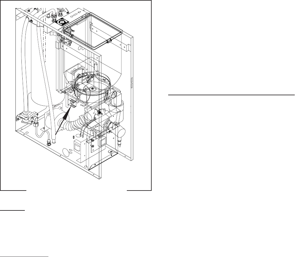
HOPPER DRIVE BOARD - FMD-1 ONLY
FIG. 21 HOPPER DRIVE BOARD
Location
The hopper drive board is located inside the
dispenser mounted on the auger motor mounting
bracket.
Test Procedures:
1. Disconnect the dispenser from the power source.
2. Disconnect the white/red wire and the white wire
from the hopper speed control board.
3. Check the voltage across the white/red wire and
the white wire with a voltmeter. With the rinse/run
switch in the run (lower) position, connect the
dispenser to the power supply. The indication
must be :
a) 120 volts ac for two wire 120 volt models.
b) 120 volts ac for three wire 120/208 volt or 120/
240 volt models.
4. Disconnect the dispenser from the power supply.
If voltage is present as described, proceed to #5.
If voltage is not present as described, refer to the wir-
ing diagram and check the dispenser wiring harness.
5. Check the voltage across the positive (red wire)
P1665
terminal and the negative (black wire) terminal on
the auger motor with a voltmeter. With the rinse/
run switch in the run (lower) position press and
hold the dispense switch. Connect the dispenser
to the power supply. After a .6 second delay the
indication must be 4.0 to 24.5 volts dc.
If voltage is present as described,the auger motor
drive is operating properly. If auger does not turn
replace the auger motor.
If voltage is not present as described, replace the
hopper drive board.
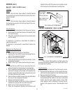
Removal and Replacement: (Refer to Fig. 2)
1. Remove hopper assy (17), and set aside for reas-
sembly.
2. Remove the four #8-32 screws securing the hop-
per support plate (12), remove plate and set aside
for reassembly.
3. Remove the four #8-32 screws, located inside the
dispener housing on the lower right front of the
auger motor mounting panel (21), securing auger
motor mounting bracket (18) and auger motor
(19) to the rear of the auger motor mounting panel
(21).
4. Disconnect the wires from the terminals on the
hopper drive board and disconnect the three pin
plug (J1) from the hopper drive board..
5. Remove auger motor mounting bracket (18), au-
ger motor (19), dust seal (20) and hopper drive
board as an assembly.
6. Remove the two #8-32 screws securing the hop-
per drive board to the auger motor mounting
bracket.
7. Remove the two spacers from the hopper drive
board and discard board.
8. Install spacers on new hopper drive board.
9. Install new hopper drive board to the auger motor
mounting bracket using two #8-32 screws..
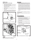
10. Refer to Fig. 22 and reconnect the wires to the
hopper drive board terminals .
11. Connect three pin plug from the potentiometer to
the hopper drive board J1. Refer to Fig. 22.
12. Install auger motor mounting bracket with auger
motor and hopper drive board to the rear of the
auger motor mounting panel using four #8-32
screws.
13. Install hopper support plate using four #8-32
screws.
14. Install hopper assy (17).
J1
29112 101598