


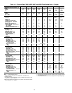
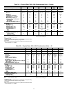
Table 2A — Physical Data; 30HL, HWA Condenserless Units — English
UNIT 30 HWA018 HWA025 HWA028 HWA035 HWA040 HL050 HL060
OPERATING WT (Approximate) − lb 740 880 960 975 1080
2070/
2120*
2130/
2190*
REFRIGERANT† — lb R-22
1.6 2.0 2.4 2.4 3.0 6.3/4.2** 5.3/5.3**
COMPRESSOR
Model No. 06DG537 06E2250 06E7265 06E7275 06E7299
06E6275,
06E2250
06E6275
Nominal Hp 15 20 25 30 35 25,20 30 (ea)
Quantity 111111(ea) 2
Cylinders Per Compressor 646666,46
Capacity Control — Standard
No. of Steps 32333 4 4
Minimum Step Capacity (%) 33 50 33 33 33 20†† 33
Capacity Control — With Optional
Hot Gas Bypass
No. of Steps 43444 5 5
Minimum Step Capacity (%) 10 10 10 10 10 10 10
Relief Valve Flow Rate — lb air/min — 15.1 15.1 15.1 15.1 15.1 15.1
COOLER
Part No. LL01SB006 LL01SB007 LL01SB009 LL01SB009 LL01SC005 10HA400654 10HA400664
Dry Weight — lb 69 81 105 105 145 726 726
Fluid Side — psig 300 300 300 300 300 150 150
Refrigerant Side — psig 430 430 430 430 430 235 235
Net Fluid Volume — Gal. 1.4 1.6 2.1 2.1 3.3 13.1 15.2
(includes nozzles)
Fluid Connections — in. Grooved End
Inlet 1
1
⁄
2
1
1
⁄
2
1
1
⁄
2
1
1
⁄
2
2
1
⁄
2
33
Outlet 1
1
⁄
2
1
1
⁄
2
1
1
⁄
2
1
1
⁄
2
2
1
⁄
2
33
CONDENSER CONNECTIONS
Refrigerant Connections — in.
Liquid Line ODS
7
⁄
8
7
⁄
8
7
⁄
8
7
⁄
8
7
⁄
8
7
⁄
8
7
⁄
8
Discharge Line ODS 1
1
⁄
8
1
1
⁄
8
1
3
⁄
8
1
3
⁄
8
1
5
⁄
8
1
3
⁄
8
1
3
⁄
8
LEGEND
ODS — Outside Diameter, Sweat
*60 Hz/50 Hz units.
†30HWA and HL units (condenserless) are shipped with a refrigerant holding
charge. Approximate cooler operating charge is shown.
**Ckt 1/Ckt 2.
††Withtransferswitch settocompressorno.2position;40% withtransferswitch
set to compressor no. 1 position.
NOTE: Operating weight includes refrigerant operating charge and weight of
fluid in the heat exchangers.
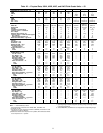
Table 2B — Physical Data; 30HL, HWA Condenserless Units — SI
UNIT 30 HWA018 HWA025 HWA028 HWA035 HWA040 HL050 HL060
OPERATING WT (Approximate) − kg 335 399 435 442 490
938/
961†
966/
993†
REFRIGERANT† — kg R-22
0.7 0.9 1.1 1.1 1.4 2.9/1.9** 2.4/2.4**
COMPRESSOR
Model No. 06DG537 06E2250 06E7265 06E7275 06E7299
06E6275,
06E2250
06E6175
Nominal kW 11.2 14.9 18.7 22.4 26.1 18.7,14.9 22.4 (ea)
Quantity 111111(ea) 2
Cylinders Per Compressor 646666,46
Capacity Control — Standard
No. of Steps 32333 4 4
Minimum Step Capacity (%) 33 50 33 33 33 20†† 33
Capacity Control — With Optional Hot Gas Bypass
No. of Steps 43444 5 5
Minimum Step Capacity (%) 10 10 10 10 10 10 10
Relief Valve Flow Rate — kg air/min — 6.8 6.8 6.8 6.8 6.8 6.8
COOLER
Part No. LL01SB006 LL01SB007 LL01SB009 LL01SB009 LL01SC005 10HA400654 10HA400664
Dry Weight — kg 31.3 36.7 47.6 47.6 65.7 330 330
Fluid Side — kPa 2069 2069 2069 2069 2069 1034 1034
Refrigerant Side — kPa 2965 2965 2965 2965 2965 1620 1620
Net Fluid Volume — L 5.3 6.1 8.0 8.0 12.5 49.9 57.5
(includes nozzles)
Fluid Connections — in. Grooved End
Inlet 1
1
⁄
2
1
1
⁄
2
1
1
⁄
2
1
1
⁄
2
2
1
⁄
2
33
Outlet 1
1
⁄
2
1
1
⁄
2
1
1
⁄
2
1
1
⁄
2
2
1
⁄
2
33
CONDENSER CONNECTIONS
Refrigerant Connections — in.
Liquid Line ODS
7
⁄
8
7
⁄
8
7
⁄
8
7
⁄
8
7
⁄
8
Discharge Line ODS 1
1
⁄
8
1
3
⁄
8
1
5
⁄
8
1
3
⁄
8
1
3
⁄
8
LEGEND
ODS — Outside Diameter, Sweat
*60 Hz/50 Hz units.
†30HWA and HL units (condenserless) are shipped with a refrigerant holding
charge. Approximate cooler operating charge is shown.
**Ckt 1/Ckt 2.
††Withtransferswitch settocompressorno.2position;40% withtransferswitch
set to compressor no. 1 position.
NOTE: Operating weight includes refrigerant operating charge and weight of
fluid in the heat exchangers.
12