


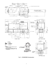
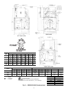
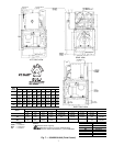
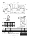
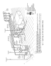
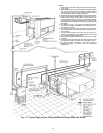

Step 5 — Make Piping Connections — See
Fig. 13 and 14 for typical piping applications.
30HK, HWC, HWS CONDENSER DESCRIPTION — All
30HWC and HWS units use a shell-and-tube condenser with
removable heads for easy tube servicing. Refrigerant is con-
tained within the shell, and water flows through the tubes.
The 30HK and HWC units use a steel shell condenser(s) with
steel tube sheets and copper tubes. The 30HWS units are
designed for sea coast applications and use a steel shell con-
denser with cupronickel tube sheets and tubes. In addition,
the 30HWS water heads utilize ‘‘sacrificial’’ zinc anodes for
condenser corrosion protection.
IMPORTANT: Inspect the zinc anodes every 3 months
for deterioration and replace as needed. Galvanic pro-
tection of the condenser is lost if the anodes are not
replaced prior to complete deterioration.
The number of tubes in the condenser(s) varies depending
on the unit size. The condensers have internal subcoolers which
provide approximately 8 F (4.4 C) for 30HK, HLunits or 13 F
(7.2 C) for 30HW units subcooling at ARI (Air Condition-
ing and Refrigeration Institute, U.S.A.) rating conditions.
30HL, HWA SYSTEM CONDENSER — For detailed con-
denser piping installation instructions for 30HL and HWA
systems, refer to separate instructions packaged with the re-
mote condenser unit(s).
Condenser refrigerant piping for 30HLand HWAunits should
be sized to minimize the amount of refrigerant required.
The 30HL and HWA units that use an air-cooled evapo-
rative condenser(s) must have adequate means for head pres-
sure control when operating below 60 F (15.6 C).
Carrier recommends that a field-supplied pressure relief
device be installed after the muffler in each discharge line.
Most local codes require the relief valve to be vented di-
rectly to the outdoors. The vent must not be smaller than the
relief valve outlet.
30HWB CONDENSER DESCRIPTION — All 30HWB units
use a brazed-plate heat-exchanger-type condenser. These heat
exchangers are made of embossed plates of acid-resistant stain-
less steel. Every other plate is reversed so that the ridges of
the herringbone pattern intersect one another on adjacent plates,
forming a lattice of contact points. These plates are vacuum-
brazed together to form a compact and pressure-resistant heat
exchanger.
After brazing, the impressions in the plates form 2 sepa-
rate systems of channels where the refrigerant and water flows
are counter-current. The number of plates varies depending
on unit tonnage. The condensers provide approximately 14°
to 18° F (8° to 10° C) liquid subcooling at the standard
Air Conditioning and Refrigeration Institute (ARI) rating
condition.
30HK, HWC, HWS CONDENSER(S) — When facing the
front of the unit, the condenser(s) is in the uninsulated shell(s)
located across the bottom of the unit. The water connections
are such that the water inlet is located on the left-hand side
(30HK) or right-hand side (30HW) of the unit. The water
inlet must ALWAYS be on the bottom of the condenser(s) to
provide the proper subcooling. The water outlet is located
on the right-hand side (30HK) or left-hand side (30HW) of
the unit. The water connections can be reversed by rotating
the heads and gaskets 180 degrees ON BOTH ENDS OF
THE CONDENSER(S).
IMPORTANT: THE WATER INLET MUST AL-
WAYS BE ON THE CONDENSER HEAD(S) THAT
HAS THE NOZZLE CONNECTION AT THE BOT-
TOM OF THE HEAD. Incorrect inlet connection will
result in poor system performance due to incorrect
subcooling.
The LIQUID-IN and LIQUID-OUT labels indicate water
connections AS SUPPLIED FROM THE FACTORY.
It is recommended that strainer with a minimum of 20 mesh
be installed ahead of the condenser water inlet(s) to prevent
debris from clogging or damaging the heat exchanger(s).
There is a pressure-relief device on the condenser(s) of all
30HK, HWC, and HWS units. Most local codes require that
this relief be vented directly to the outdoors.
NOTE: The relief line must not be smaller than the relief
valve outlet. Be sure to provide a way of draining and ser-
vicing the unit.
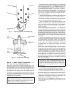
THUMB-SCREW
BRAKE
Fig. 11 — Factory-Installed Unit Wheels (4)
Fig. 12 — Compressor Mounting
13