


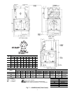
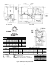
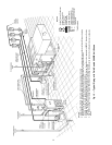
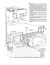
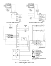
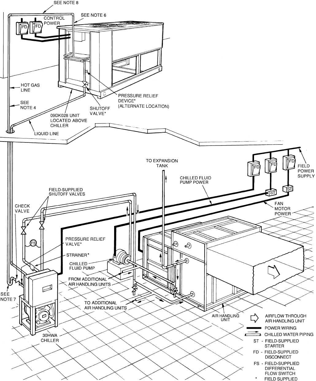
Fig. 14 — Typical Piping with Air-Cooled 30HWA with Remote 09DK Unit Shown
NOTES:
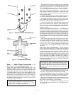
1. Chiller must be installed
levelly
to maintain proper compres-
sor oil return.
2. Wiringandpipingshown aregeneralpoints-of-connectionguides
only and are not intended for a specific installation. Wiring
and piping shown are for a quick overview of system and are
not in accordance with recognized standards.
3. Allwiringmust complywith applicablelocal andnational codes.
4. All piping must follow standard piping techniques. Refer to
Carrier System Design Manual part 3, Carrier E20-IIா soft-
ware Refrigerant Piping program, or appropriate ASHRAE
(American Society of Heating, Refrigeration, and Air Condi-
tioning Engineers)handbook fordetails onproper pipingsizes
and design.
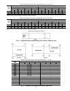
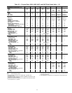
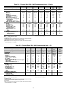
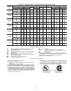
5. See Table 3 on page 17 for minimum system fluid volume.
This system may require the addition of a holding tank to en-
sure adequate volume.
6. Hotgas lines shouldrise above refrigerant levelin condenser
circuit. Doubleriser maybe required; checkcompressor mini-
mum capacity.
7. Trap should be installed on hot gas lines to prevent con-
denser oil and refrigerant vapor migration from accumulating
on compressor heads during off cycle.
8. Pitch all horizontal lines downward in the direction of refrig-
erant flow.
9. For pipinglengths greater than 50 ft, provide supportto liquid
and gas lines near the connections to the condenser coil.
10. For pressure relief requirements, see latest revision of
ASHRAE Standard 15, Safety Code for Mechanical
Refrigeration.
15