


DISCHARGE LINE CHECK VALVE — On all 30HL, HWA
units, a factory-supplied check valve is shipped with the unit
(two valves are provided for 30HLunits). The check valve(s)
should be installed in the discharge line(s) downstream from,
but close to, the compressor muffler. Install the valve in any
position except bonnet down.
The check valve(s) prevents backwards-migration of re-
frigerant from the condenser(s) to the compressor(s) and cooler
during the compressor off cycle.
HOT GAS BYPASS VALVE — On units equipped with the
factory-installed capacity reduction option (30HW only), a
hot gas bypass valve is located between the discharge line
and the cooler entering-refrigerant line. A solenoid valve is
installed in the equalizer line of the hot gas valve to allow
the temperature control to cycle the hot gas bypass function.
The amount of capacity reduction achieved by the hot gas
bypass valve may be altered by adjusting the spring tension
of the hot gas bypass valve. The total unit capacity should
not be reduced below 10% of the nominal rating.
LIQUID LINE SOLENOID VALVE (30HL ONLY) — The
solenoid valve closes when its circuit is inoperative, either
from capacity control or from any safety trip.
PRESSURE RELIEF DEVICES — All 30HK, 30HL, and
30HW units are equipped with a compressor pressure relief
valve located on the crankcase of the 06E compressor units
(except for the 30HW018 units which have a compressor
displacement less than 50 cfm). The pressure relief valve opens
at 450 psig (3103 kPa).
The 30HK,HWC, and HWS units are also equipped with
a high-side refrigerant pressure relief valve on the shell and
tube condenser. The valve is set to open at the working pres-
sure of the condenser, as shown in Table 7.
The 30HWB does not have a condenser pressure relief
valve, because the brazed-plate condenser is not considered
a pressure vessel, as defined in ANSI/ASHRAE 15 (Ameri-
can National Standards Institute/American Society of Heat-
ing, Refrigerating, and Air Conditioning Engineers) safety
code requirements.
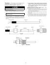
For 30HL and HWA condenserless units, pressure relief
devices designed to relieve at 450 psig (3103 kPa), must be
field-supplied and installed in the discharge line piping after
the muffler in accordance withANSI/ASHRAE 15 safety code
requirements. Additional pressure relief valves, properly se-
lected, must be field-supplied and installed to protect high
side equipment and may be required by applicable codes.
Most codes require that a relief valve be vented directly
to the outdoors. The vent line must not be smaller than the
relief valve outlet. The condenser relief valves have a
5
⁄
8
-in.
SAE (Society of Automotive Engineers, U.S.A.) flare connec-
tion. The compressor relief valves have a
3
⁄
8
-in. SAE Flare
connection. Consult ANSI/ASHRAE 15 for detailed infor-
mation concerning layout and sizing of relief vent lines.
All units have a factory-installed fusible plug in the suc-
tion line which relieves on a temperature rise at 170 F
(77 C) and one in the liquid line which relieves at 210 F (99 C).
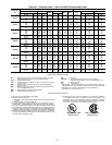
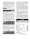
Table 7 — Pressure Relief Valve Settings
UNIT
PRESSURE RELIEF VALVE SETTINGS
Psig kPa
30HK 385 2655
30HWC 365 2517
30HWS 335 2310
Compressor and Unit Protective Devices
CIRCUIT BREAKER — There is a single circuit breaker
per compressor in each unit. The circuit breaker(s) protects
the compressor(s) against overloading, locked rotor condi-
tions, and primary single phasing. If the circuit breaker(s)
trips, determine the cause and correct it before resetting the
breaker(s).
COMPRESSOR INTERNALTHERMAL PROTECTION —
On the 30HW018 units, there is a sensor imbedded in
the compressor windings to detect an overtemperature
condition.
The thermostat opens and shuts off the compressor if the
discharge gas temperature exceeds 295 ± 5° F (146 ± 2.8° C).
The thermostat will reset when the temperature drops to ap-
proximately 250 F (121 C). However, the control module
will keep the unit locked off until control power is manually
cycled off, then back on.
NOTE: Compressor overtemperature protection for 30HK,
HL units is accomplished by high and low pressure switches
and circuit breakers which are external to the compressors.
CRANKCASE HEATER
Never open or disconnect any switch that energizes the
crankcase heater, unless the unit is being serviced or will
be shut down for an extended period. After service or
shutdown, energize the crankcase heater for 24 hours
before starting the compressor.
IMPORTANT: The crankcase heater is located in the
bottom corner of the compressor and held in place by
a bracket. The heater must be tight to prevent it from
backing out of the heater well. The heater eventually
burns out if exposed to the air for an extended period.
The heater in each compressor prevents absorption of liq-
uid refrigerant by the compressor oil when the compressor
is not operating. The heater is wired into the normally closed
contacts of the compressor control relay so that it energizes
only when the compressor is not operating. The heater is
125 w, 115 v on all 60 Hz units; 230 v on 50 Hz 30HK, HL
units; and 115 v on 50 Hz 30HW units.
OIL PRESSURE SAFETY SWITCH (OPS) — One OPS per
compressor is standard on all 30HL and HWA units, and on
all units equipped with the medium temperature brine op-
tion. One is located in each compressor terminal box with
capillaries to the crankcase and oil pump. The switch is also
offered as an accessory (part number 30HW900006) for stand-
ard 30HK, HWB, HWC, and HWS units. When used, the
OPS is monitored by the unit control module. If at any time
after the compressor is started, the OPS is open for more
than 2 minutes, the compressor shuts down and is locked off
until control power is manually cycled to OFF, then back to
the ON position. The OPS cuts out at5±1psig (34.5 ±
6.9 kPa), and has a maximum cut-in of 9.5 psig (65.5 kPa).
Check Unit Safeties
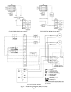
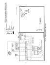
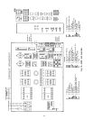
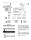
CONTROL MODULE — The unit control module is lo-
cated in the control section of the control box. See Fig. 19
and 20. It performs several functions. The control module
has a built-in compressor anti-short-cycle timer which will
not allow a compressor to restart until 5 minutes have elapsed
since the previous shutdown.
On 30HL and HWA units (and 30HK, HWB, HWC, and
HWS units equipped with the oil pressure safety switch [OPS]
accessory), the compressor oil pressure and low-pressure
switch(es) (LPS) are monitored through the control module.
The unit is allowed to remain operational as long as the OPS
and/or LPS have not been open for more than 2 minutes af-
ter a compressor has started. After start-up, if the OPS and/or
LPS are open for more than 2 minutes, the control module
shuts down the compressor and places the unit in a lockout
condition. The control module activates the fault indication
circuit, and the unit service lamp is illuminated. The unit
cannot be restarted until control power is manually cycled to
OFF, then to ON.
28