


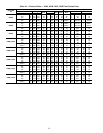
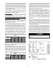
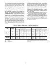
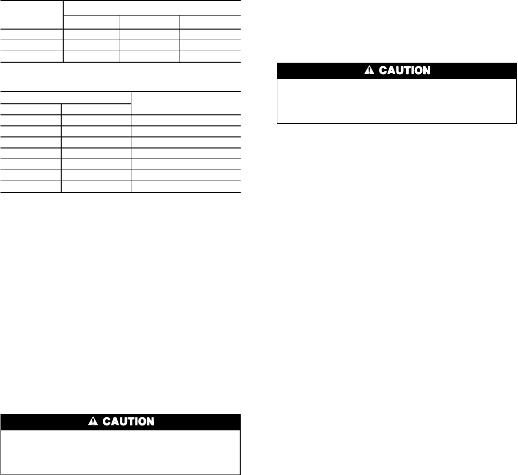
Table5—Typical Deadband Requirements
UNIT
CAPACITY
STEPS
COOLER DESIGN RANGE, F (C)
5.0 (2.8) 10.0 (5.6) 15.0 (8.3)
2 1.3 (0.7) 2.5 (1.4) 3.8 (2.1)
3 0.8 (0.4) 1.7 (0.9) 2.5 (1.4)
4 0.6 (0.3) 1.3 (0.7) 1.9 (1.1)
Table 6 — Deadband Setting
MIN. REQUIRED DEADBAND
DEADBAND SETTING (F)
FC
0.5 to 1.5 0.28 to 0.83 1.0
2.0 1.11 2.0
2.5 1.39 2.5
3.0 1.67 2.8
3.5 1.94 3.0
4.0 2.22 3.7
4.5 2.50 4.0
10. Check compressor oil charge (should be visible in
oil sight glass). Refer to Check Oil Charge section on
page 27.
11. Be sure the compressor crankcase heater is warm (heater
should be on for 24 hours before starting the compres-
sor). The crankcase heater must be firmly locked into
the compressor crankcase.
12. Be sure the compressor is floating freely on the com-
pressor springs (see Step 4 — Check Compressor Mount-
ing and Connections section on page 3).
13. For 30HL and HWA units with remote condenser, check
the condenser fans for correct rotation. See instructions
shipped with the condenser.
14. Be sure the unit is fully charged with refrigerant (see
Check Refrigerant Charge section below).
15. If unit is a brine unit, check to ensure proper brine con-
centration is used to prevent freezing.
Check Refrigerant Charge
When adding or removing refrigerant charge, circulate
water through condenser and cooler at all times to pre-
vent freezing. Freezing damage is considered abuse and
is not covered by Carrier warranty.
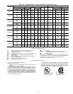
The 30HK, HWB, HWC, and HWS units are shipped with
a full refrigerant charge (see Tables 1A-2B). However, if it
is necessary to add refrigerant, operate the unit for some time
at full capacity and then add charge until the sight glass is
clear of bubbles. For maximum liquid subcooling, liquid level
should be up to condenser end (30HK, HWC, HWS units
only). This usually requires additional refrigerant charge be-
yond the amount to clear sight glass.
The 30HL and HWAunits (condenserless) are shipped with
a refrigerant holding charge only. After chiller assembly is
completed in the field, system must be fully charged. While
the unit is running at full capacity, add refrigerant until the
sight glass is clear. R-22 is the normal refrigerant.
Do not open the liquid valve or the compressor discharge
valve until there is a charge in remainder of system. A posi-
tive pressure indicates a charge in system. With the unit op-
erating at full load, check liquid line sight glass to be sure
the unit is fully charged (bubbles in the sight glass indicate
the unit is not fully charged).
If there is no refrigerant vapor pressure in the system, the
entire system must be leak tested.After repairing leaks, evacu-
ate the system before recharging. Follow approved evacu-
ation procedures when removing refrigeration. Release re-
maining pressure to an approved evacuated cylinder.
The liquid charging method is recommended for com-
plete charging or when additional charge is required.
Be careful not to overcharge the system. Overcharging
results in higher discharge pressure with higher cooling
water consumption, possible compressor damage, and
higher power consumption.
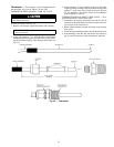
LIQUID CHARGING METHOD — Add charge to the unit
through the liquid line service valve. Never charge liquid
into the low-pressure side of the system.
1. Frontseat (close) condenser liquid line shutoff valve.
2. Connect a refrigerant cylinder loosely to the charging valve
connection of the liquid line shutoff valve. Purge the charg-
ing hose and tighten the connections.
3. Open the charging valve.
4. If the system has been dehydrated and is under vacuum,
break the vacuum with refrigerant gas. For R-22, build
up system pressure to 58 psig and 32 F (400 kPa and
0° C). Invert the refrigerant cylinder so that the liquid
refrigerant will be charged.
5. a. For complete charge of 30HK, HWB, HWC, and HWS
units, follow charging by weight procedure.When charge
is nearly full, complete the process by observing the
sight glass for clear liquid flow. The use of sight glass
charging is valid only when unit is operating at full
capacity (no unloaders energized).
b. For complete charge of 30HLand HWA units or where
refrigerant cylinder cannot be weighed, follow charg-
ing by sight glass procedure. The use of sight glass
charging is valid only when unit is operating at full
capacity (no unloaders energized).
6. a. The 30HL and HWA condenserless units are shipped
with a holding charge only. After installation with the
field-supplied system high side, the complete system
should be charged until the sight glass is clear (with
the unit running at full capacity). To achieve maxi-
mum system capacity, add additional charge equal to
the difference between the condenser optimal charge
and the condenser minimum charge, which can be ob-
tained from the charge data provided in the condenser
installation instructions.
b. To ensure maximum performance of 30HWB units,
raise the compressor saturated discharge temperature
(SDT) to approximately 105 F (40.6 C) by throttling
the condenser water intake. Add charge until there is
approximately 15 to 17° F (8.3 to 9.4° C) of system
subcooling (SDT minus actual temperature entering the
thermostatic expansion valve).
c. To ensure maximum performance of 30HK, HWC, and
HWS units, raise the compressor saturated discharge
temperature (SDT) to approximately 103 F (39.4 C)
by throttling the condenser water intake. Add charge
until there is approximately 8 to 10° F (4.4 to 5.6° C)
for 30HK units or 12 to 14° F (6.7 to 7.8° C) for 30HWC,
HWS units of system subcooling (SDT minus actual
temperature entering the thermostatic expansion valve).
26