


If rapid cycling of the capacity steps occurs, the deadband
setting is too low and should be raised to the point that rapid
cycling will cease.
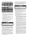
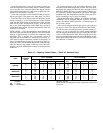
If a cooler design range other than those shown in
Table 5 is desired, determine the setting by using the fol-
lowing formula and Table 6:
Minimum Required Unit Deadband:
Minimum Deadband = (Cooler Design ⌬t÷
(2 x no. of Capacity Steps)
= F (C)
The lights on the temperature controller will indicate the
status of the control. If the green light labeled ABOVE SET
POINT is illuminated, the controller will add steps of ca-
pacity, if additional steps are available. If the yellow light
labeled BELOW SET POINT is illuminated, the controller
removes steps of capacity.
The temperature controller also has a red light labeled OUT
OF RANGE that indicates the system load was reduced faster
than the controller could remove stages. If this occurs, the
unit shuts down to avoid cooler freeze-up.
Once the temperature rises back into the control band, the
unit restarts automatically. This also occurs if the therm-
istor fails in the open mode. In the case of a thermistor fail-
ure, the unit does not restart until the thermistor is replaced.
FREEZE-UP PROTECTION
On medium temperature brine units, the brine must be
properly mixed to prevent freezing at a temperature of
at least 15 F (8.3 C) below the leaving-fluid temperature
set point. Failure to provide the proper brine mixture is
considered abuse and may void the Carrier warranty.
All units have the following 2 modes of freeze-up
protection.
1. The temperature controller protects the system from freeze-up
due to rapid loss of load and from low fluid flow by rap-
idly removing all steps of capacity and shutting down the
compressor if an out-of-range condition exists. This nor-
mally occurs if the leaving-fluid temperature drops 6 to
7° F (3.3 to 3.9° C) below the temperature controller set
point. Set point range is 40 to 60 F (4.4 to 15.6 C) for
standard units and 15 to 39 F (−9.4 to 3.9 C) for units
with medium temperature brine option.
2. The low-pressure switch provides a back-up cooler freeze-up
protection system. The low-pressure switch shuts down
the unit when the suction temperature drops to a point
where the cooler will freeze up.
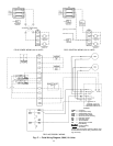
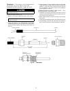
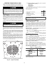
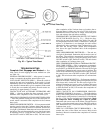
LOSS-OF-COOLER-FLOW PROTECTION — A proof-of-
cooler-flow device (accessory flow switch) must be used with
all 30HK, HL, HW chillers. The device should be a differ-
ential pressure type device and should be set to shut the unit
off if cooler gpm drops below 1.5 times the nominal unit
tonnage. Carrier accessory flow switch, part number
30HW900003 is available for this purpose. See page 19 and
Fig. 17 and 18.
COMPRESSOR GROUND FAULT SENSOR — The ground
fault sensor accessory (Part No. 30HW900004) monitors all
phases of the 3-phase power supply to the compressor. If a
short to ground is sensed by the sensor, the compressor au-
tomatically shuts down. This prevents contamination of the
refrigeration system from acid formation. The compressor
shuts down when a 2.5 ± 2 amps ground current is sensed by
a toroid installed around the compressor power leads. The
unit control module locks the compressor off until the circuit
power is cycled to OFF, and then ON. For installation de-
tails, see the instructions included with the accessory
package.
NOTE: Two accessory packages are required for 30HK, HL
units.
UNIT OPERATION
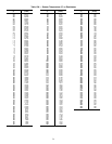
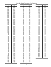
Capacity Control and Operating Sequence —
The 30HW units have a multiple-step temperature control-
ler, factory set to maintain capacity control through leaving
chilled fluid temperature. The controller has 4 capacity steps.
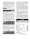
All 30HK, HL units have 4 capacity steps as standard. The
30HW018 and 028-040 units have 3 steps as standard, with
a fourth step available as a factory-installed option. The
30HW025 units have 2 steps of capacity as standard with a
third step available as a factory-installed option. All units
have electric solenoid operated unloaders. See Tables 10 and
11 for capacity control steps of each unit.
At initial start-up, assume that all safety devices are sat-
isfied and there is a call for cooling.
30HK,HL UNITS — Close the compressor circuit breaker
and turn the ON-OFF switch to the ON position.
In approximately 5 minutes, the lead compressor starts and
the unloaders are energized (compressor unloads when com-
pressor unloader solenoid is energized). On 30HL units, the
liquid line solenoid valve will remain closed for the first
10 seconds of compressor operation. The low-pressure and
oil pressure switches are bypassed for 2 minutes. At the end
of the 2-minute bypass period, the low-pressure and oil pres-
sure switches are active in the control circuit.
Approximately 30 seconds (high setting) or 3 minutes (low
setting) later, depending on the sample rate setting, the lag
compressor starts and the unloaders are energized (compres-
sor unloads when compressor unloader solenoid is ener-
gized). On 30HL units, the liquid line solenoid valve will
remain closed for the first 10 seconds of compressor opera-
tion. The low-pressure and oil-pressure switches are by-
passed for 2 minutes. At the end of the 2-minute bypass pe-
riod, the low-pressure and oil-pressure switches are active in
the control circuit.
Approximately 30 seconds (high setting) or 3 minutes (low
setting) later, depending on the sample rate setting, the lead
compressor is loaded (unloader solenoids deenergized).
Approximately 30 seconds (high setting) or 3 minutes (low
setting) later, depending on the sample rate setting, the lag
compressor is loaded (unloader solenoids deenergized).
When the load is satisfied and the leaving fluid tempera-
ture falls below the set point, the last stage activated is dropped
immediately. If the leaving fluid temperature still remains
below the set point, then the control drops an additional stage
every 30 (high setting) or 180 (low setting) seconds, de-
pending on the sample rate setting.
30