


Check Oil Charge — The compressor(s) is factory-
charged with oil. If oil is visible in the compressor sight
glass(es), check the unit for operating readiness as described
in Initial Check section (page 25), then start the unit. Ob-
serve oil level and add oil, if required, to bring the oil level
in the compressor crankcase(s) to between
1
⁄
8
and
3
⁄
8
of the
sight glass(es) during steady operation.
TO ADD OIL
1. Close the suction shutoff valve and pump the compressor
crankcase down to between zero and 2 psig (zero to
13.8 kPa) (the low-pressure switch must be jumpered).
Wait a few minutes and repeat as needed until the pres-
sure remains between zero and 2 psig (zero to 13.8 kPa).
2. Close the discharge shutoff valve.
3. Remove the oil-fill plug above the compressor sight glass,
add oil through the plug hole, and replace the plug.
4. After opening the suction and discharge service valves,
remove low-pressure switch jumper, run the compressor
for about 20 minutes, and check the oil level.
Use only Carrier-approved compressor oil:
Petroleum Specialties, Inc. ................Cryol 150*
Texaco, Inc. .........................Capella WF-32
Witco Chemical Co. .....................Suniso 3GS
*Factory charge.
Do not reuse drained oil, and do not use any oil that has
been exposed to the atmosphere.
TO REMOVE OIL
The crankcase will be under slight pressure. Be careful
not to lose the entire oil charge. Gloves and eye pro-
tection must be worn.
Pump down the compressor to between zero and 2 psig
(zero to 13.8 kPa). Loosen the oil drain valve located in the
compressor base to allow the oil to seep out past plug threads.
Be careful not to remove plug; the entire oil charge may be
lost. Small amounts of oil can be removed through oil pump
discharge connection.
START-UP AND OPERATION
Operation Checks —
Start-up should be performed only
under supervision of an experienced refrigeration techni-
cian. Refer to Start-Up Checklist on pages CL-1 to CL-4.
Remove and save the checklist for future reference.
1. Crankcase heater must be energized for at least 24 hours
before the chiller is started.
2. Open all system valves that may have been closed during
or after charging.
3. Check air-handling equipment, chilled water (fluid) and
condenser pumps, and any other equipment connected to
the chiller.
4. Start the unit by moving the ON-OFF switch to the ON
position.
5. Check all controls for proper operation. Follow Start-Up
Checklist procedures in these instructions.
6. Adjust the water regulating valve (where used) to obtain
the most economical head pressure (based on the relative
cost of water and electricity). Head pressure is normally
200 to 230 psig (1379 to 1586 kPa) for 30HK,HL units,
and 195 to 226 psig (1344 to 1558 kPa) for 30HW units
when using R-22 refrigerant.
7. Check the cooler leaving chilled water temperature to see
that it remains well above 32 F (0° C), or the brine freez-
ing point if the unit is a medium temperature brine unit.
8. Recheck compressor oil level (see Check Oil Charge sec-
tion on this page). Add or remove oil to achieve the level
required during steady operation.
Operating Limitations
Do not operate with cooler leaving chiller water (fluid)
temperature (LCWT) below 40 F (4.5 C) for the stan-
dard units, or below 15 F (−9.4 C) for units factory built
for medium temperature brine.
HIGH COOLER LEAVING CHILLED WATER (FLUID)
TEMPERATURES (LCWT) — During start-up with cooler
LCWT above approximately 60 F (16 C), the unit expansion
valve will limit suction pressure to approximately 90 psig
(620 kPa) to avoid overloading the compressor.
LOW COOLER LCWT — For standard units, the LCWT
must be no lower than 40 F (4.5 C). If the unit is the factory-
installed optional medium temperature brine unit, the cooler
LCWT can go down to 15 F (−9.4 C).
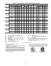
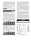
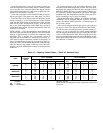
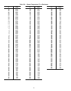
MAIN POWER SUPPLY — Minimum and maximum ac-
ceptable supply voltages are listed in Tables 4A and 4B.
Unbalanced 3-Phase Supply Voltage — Never operate a mo-
tor where a phase imbalance between phases is greater than
2%. To determine percent voltage imbalance, see Unbal-
anced 3-Phase Supply Voltage section on page 19.
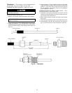
Check Refrigerant Feed Components
THERMOSTATIC EXPANSION VALVE (TXV) — The TXV
controls the flow of liquid refrigerant to the cooler by main-
taining constant superheat of vapor leaving the cooler. There
is one valve per refrigerant circuit. The valve(s) is activated
by a temperature-sensing bulb(s) strapped to the suction line(s).
The valve(s) is factory-set to maintain between 8° and
10° F (4.4° and 5.6° C) of superheat leaving the cooler. Check
the superheat during operation after conditions have stabi-
lized. If necessary, adjust the superheat to prevent refriger-
ant floodback to the compressor.
FILTER DRIER — The function of the filter drier is to main-
tain a clean, dry system. The moisture indicator (described
below) indicates any need to change the filter drier. The fil-
ter drier is a sealed-type drier. When the drier needs to be
changed, the entire filter drier must be replaced.
NOTE: The 30HK, HL units have 2 filter driers; one per
circuit.
MOISTURE-LIQUID INDICATOR — The indicator is lo-
cated immediately ahead of the TXV to provide an indica-
tion of the refrigerant moisture content. It also provides a
sight glass for refrigerant liquid. Clear flow of liquid refrig-
erant (at full unit loading) indicates sufficient charge in the
system. Bubbles in the sight glass (at full unit loading) in-
dicate an undercharged system or the presence of noncon-
densables. Moisture in the system, measured in parts per million
(ppm), changes the color of the indicator as follows:
Blue (safe) — Moisture is below 45 ppm
Light Violet (caution) — 45 to 180 ppm
Pink (wet) — above 180 ppm
The unit must be in operation at least 12 hours before the
moisture indicator gives an accurate reading, and must be in
contact with liquid refrigerant. At the first sign of moisture
in the system, change the corresponding filter drier.
NOTE: The 30HK, HL units have 2 indicators; one per
circuit.
LIQUID LINE SERVICE VALVE — This valve provides a
refrigerant charging port and, in combination with the com-
pressor discharge service valve(s), allows the refrigerant to
be pumped into the high side of the system.
27