


The control module also monitors the high-pressure
switch(es) and compressor internal thermal protection (30HW).
If at any time one or both of these switches opens, the con-
trol module shuts down the compressor and places the unit
in a lockout condition. The control module activates the fault
indication circuit, and the unit service lamp is illuminated.
The unit cannot be restarted until control power is manually
cycled to OFF, then to ON.
If the unit shuts down on an automatic reset switch, such
as the temperature controller, the compressor will be al-
lowed to restart when the switch closes and the control mod-
ule anti-short-cycle time has elapsed.
For Servicing Only — To speed up the 5-minute anti-short
cycle, a jumper may be placed between terminals T1 and T6
of the control module.
This jumper must be removed after servicing is complete.
Failure to remove this jumper is considered abusive treat-
ment and will void the Carrier warranty.
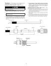
HIGH-PRESSURE SWITCH — A high-pressure switch is
provided to protect each compressor and refrigeration sys-
tem from unsafe high pressure conditions. See Table 8 for
high-pressure switch settings.
The high-pressure switch is mounted in the discharge side
of each compressor.A snubber is provided between the com-
pressor discharge manifold and the high-pressure switch to
prevent pressure pulsations from damaging the switch.
If an unsafe, high-pressure condition should exist, the switch
opens and shuts off the affected compressor. The unit control
module prevents the unit from restarting. The unit will not
restart until control power is manually cycled off, then on.
To check operation of the switch, slowly close the com-
pressor discharge shutoff valve until the compressor shuts
down. The switch should open at the pressure corresponding
to the appropriate switch setting as shown in Table 8.
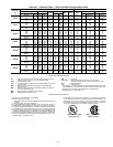
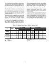
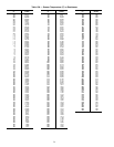
Table 8 — Factory Settings, High-Pressure Switch
(Fixed)
UNIT
30
CUTOUT CUT-IN
Psig kPa Psig kPa
HK, HWS 280 ± 10 1931 ± 69 180 ± 20 1241 ± 138
HL, HWB, HWC 375 ± 10 2585 ± 69 275 ± 20 1896 ± 138
HWA 395 ± 10 2723 ± 69 298 ± 20 2054 ± 138
Reopen the compressor discharge shutoff valve, and cycle
the unit ON-OFF switch to OFF, then ON. The unit should
restart after the compressor anti-short-cycle delay, built into
the unit control module, expires.
LOW-PRESSURE SWITCH —Alow-pressure switch is pro-
vided to protect each compressor and system from a loss of
refrigerant. The low-pressure switch(es) also provides freeze
protection for the cooler. The low-pressure switch(es) is non-
adjustable. See Table 9 for low-pressure switch settings. One
switch is used for standard units, and a different switch is
used for units with the brine option.
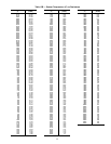
Table 9 — Factory Settings, Low-Pressure Switch
(Fixed)
UNIT
TYPE
CUTOUT CUT-IN
Psig kPa Psig kPa
STANDARD 42±3 290±21 57±5 393±34
BRINE 27±3 186±21 44±5 303±34
To check operation of the low-pressure switch, slowly close
the suction service valve and allow the affected compressor
to pump down. The compressor should cut out when the suc-
tion pressure falls below the low-pressure switch cutout set-
ting. Open the suction service valve. The compressor should
restart after the low-pressure switch closes, and the com-
pressor anti-short-cycle delay expires.
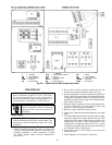
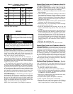
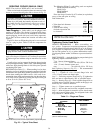
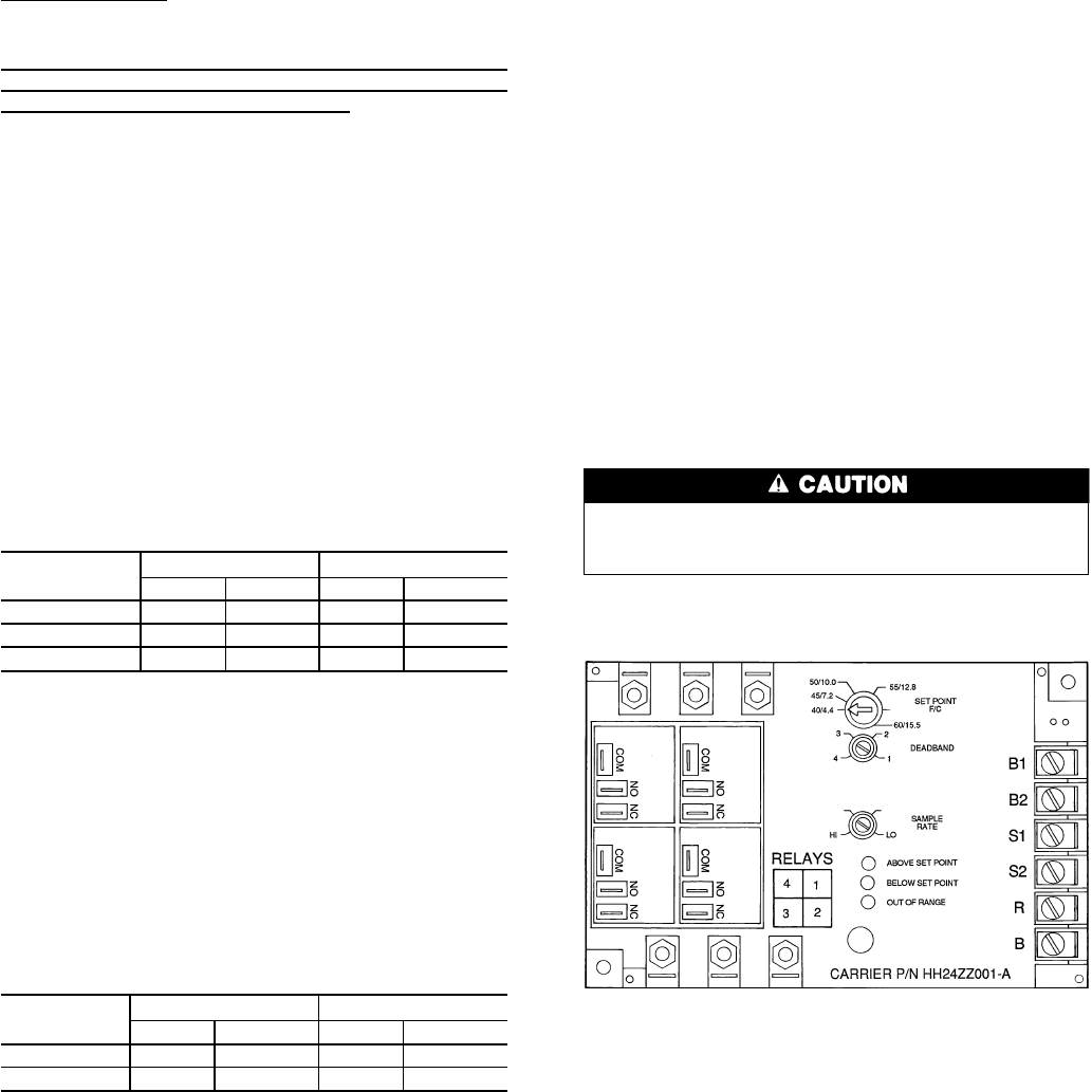
CHILLED FLUID TEMPERATURE CONTROLLER — All
units are equipped with a temperature controller (see
Fig. 21) which is capable of controlling up to 4 steps of ca-
pacity. A thermistor installed inside the cooler supplies the
input to the controller. The temperature controller can op-
erate a system with cooling ranges (entering cooler fluid tem-
perature minus leaving cooler fluid temperature) of 5° to
15° F (2.8° to 8.3° C), and with a range of set points from
40 to 60 F (4.4 to 15.5 C) for standard units, and 15 to
39 F (−9.4 to 3.9 C) for units with the medium temperature
brine option.
The set point of the temperature controller should be ad-
justed to the desired leaving cooler fluid temperature, and
verified by using a thermometer placed in the leaving-cooler
piping. The amount of deadband around the set point value
is adjusted through the use of the deadband adjustment knob
on the temperature controller. See Tables 5 and 6 for the cor-
rect setting of the deadband.
The unit should then control the average leaving-fluid tem-
perature to this setting. If the leaving-fluid temperature does
not correspond to the desired set point, slightly readjust the
controller set point knob until the desired leaving-fluid tem-
perature is obtained. The temperature controller has an ad-
justable 30-second (HI position) to 3-minute (LO position)
sample rate knob. The sample rate knob should always be
set at LO position (fully clockwise) for 30HK, HLunits, and
at HI position (fully counterclockwise) for 30HW units.
Do not force the knob dials past the stops. This
could cause loss of control point and damage to the
controller.
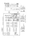
LEGEND
COM — Common
NC — Normally Closed
NO — Normally Open
Fig. 21 — Temperature Controller
29