


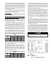
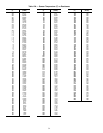
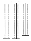
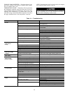
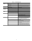
Thermistor — The resistance at various temperatures for
the thermistor are given in Tables 12A and 12B.
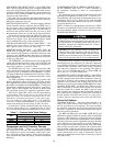
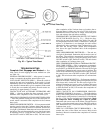
THERMISTOR REPLACEMENT, 30HK, HL UNITS
Thermistors are installed directly in fluid circuit. Drain
fluid before removing.
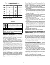
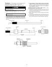
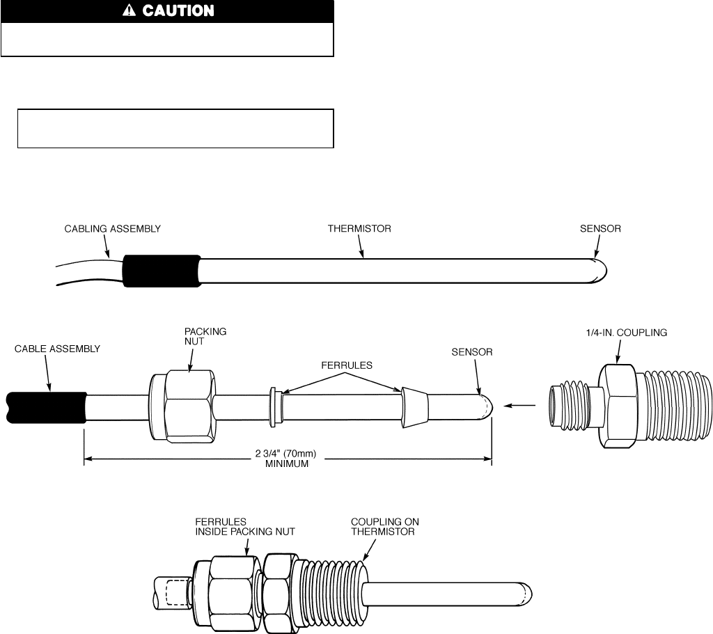
Proceed as follows (see Fig. 22):
1. Remove and discard original thermistor and coupling.
IMPORTANT: Do not diassemble new coupling. In-
stall as received.
2. Apply pipe sealant to
1
⁄
4
-in. NPT threads on replacement
coupling and install in place of original. Do not use a pack-
ing nut to tighten coupling. This damages the ferrules (see
Fig. 22).
3. Insert thermistor T1 into coupling body to its full depth.
Tighten packing nut finger tight to position ferrules, then
tighten 1
1
⁄
4
turns more using a back-up wrench. Ferrules
are not attached to the sensor, which can be withdrawn
from coupling for service.
THERMISTOR REPLACEMENT, 30HW UNITS — To re-
place the thermistor, follow these steps:
1. Disconnect the existing thermistor from the S1 and S2
terminals of the temperature controller (located in the con-
trol section of the control box).
2. Remove the thermistor from the well in the cooler leaving-
fluid cacity.
3. Insert the replacement thermistor into the thermistor well.
4. Run thermistor wires into the control box and connect to
the S1 and S2 terminals of the temperature controller.
Fig. 22 — Thermistor
33