


30HWB CONDENSER — When facing the back of the unit,
the condenser is the uninsulated heat exchanger located on
the right-hand side. The water connections are on the right-
hand side of the heat exchanger with the LIQUID-IN con-
nection at the bottom, and the LIQUID-OUT connection at
the top.
A strainer with a minimum of 20 mesh must be installed
ahead of the condenser water inlet to prevent debris from
clogging or damaging the heat exchanger.
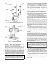
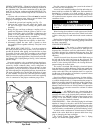
To install the grooved end coupling (see Fig. 15):
1. Lubricate the gasket lips and stretch the gasket over
the end of the pipe. Avoid twisting the gasket when
installing.
2. Bring the pipe and heat exchanger coupling ends to-
gether into alignment. Slide the gasket so that it is cen-
tered over the ends. Apply a light film of lubricant to the
gasket, or to the gasket recess of the coupling housing.
Avoid twisting the gasket during installation.
3. Seat the coupling halves over the gasket and install the
nuts and bolts. Tighten the nuts equally on both sides.
4. Alternately tighten the nuts with a wrench to draw
the coupling halves together uniformly. The joint is now
complete.
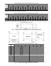
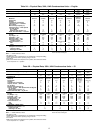
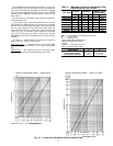
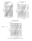
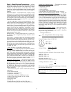
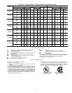
30HK, HWB, HWC, HWS UNITS — In order to minimize
the water pressure drop in the system, use as few bends as
possible in the field water piping, and run the lines as short
as possible. Size the water lines according to the available
pump pressure (not necessarily the connection size), espe-
cially on cooling tower applications. See Carrier System De-
sign Manual, Part 3, Piping Design. See Fig. 16 for condenser
pressure drops.
Set water regulating valve to maintain design head pres-
sure. Do not adjust to compensate for high head pressures
caused by fouled condenser tubes, excess refrigerant, or
the presence of noncondensables. Due to changes in water
temperature, it may be necessary to adjust the valve season-
ally.After adjusting for design head pressure, shut unit down.
The water regulating valve should shut off the flow of water
in a few minutes. If it does not, raise head pressure setting.
Make sure that the capillary tube from each water regulating
valve is connected to the proper condenser purge valve.
Provide a means for draining the system in the winter (if
not used) and for maintenance.
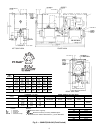
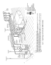
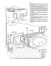
Accessory steel manifold packages for inlet and outlet con-
denser water are available for 30HK units. Each manifold is
furnished in 2 sections, to be field welded as shown in
Fig. 4. Manifolds should not be used where regulating valves
are required because separate valves must be used on each
condenser circuit.
Retighten all condenser head bolts before filling system
with water. Torque bolts to a maximum of 40 to
45 ft-lb.
Water leaving the condenser is under pressure and should
not be connected directly into sewer lines. Check local codes.
A 3/8-in. drain plug is located in the head at each condenser
end.
Refer to Pressure Relief Devices and Discharge Line Check
Valve sections on page 28, concerning piping connections
for these components.
COOLER DESCRIPTION
30HK, HL Units — The cooler is a direct-expansion type
with removable heads and is partitioned for multi-pass re-
frigerant flow. Fluid flow across the tube bundle is directed
by baffles designed for minimum fluid-pressure drop. The
tubes have integral internal fins for maximum heat transfer
efficiency.
Viewed from unit front, the return chilled fluid enters at
the left end of the cooler and leaves at the right end. The
sensing bulb for the factory-supplied fluid temperature con-
troller is in the leaving-fluid nozzle; the leaving-fluid tem-
perature being the control point.
The cooler is insulated with a flexible, closed-cell plastic
foam insulation of suitable thickness. Fluid vapor cannot pen-
etrate the cellular structure to condense either within cells or
on the cooler shell. Thus, the insulation itself is a vapor bar-
rier. Because of the toughness of insulation, a protective sheet
metal covering is not necessary.
Special modification may be necessary for brine chillers.
Contact your Carrier representative for details. For calcium
or sodium chloride brines, it is important that the proper in-
hibitors be carefully selected for protection of the copper tubes.
Refer to the publications of the Calcium Institute or the
Mutual Chemical Division of Allied Chemical Corporation
for information on corrosion control for calcium or sodium
chloride systems.
30HW Units — All 30HW units use a brazed-plate heat-
exchanger type cooler. The heat exchanger is constructed es-
sentially the same as the brazed-plate condenser used on
30HWB units. See 30HWB Condenser Description section
on page 13 for more details. Similar to the condenser, the
cooler can only be chemically cleaned.
COOLER PIPING — Plan cooler fluid piping for minimum
number of changes in elevation, and for the fewest number
of bends as possible. Install manual or automatic vent valve
at high points in the line. Maintain system pressure by using
a pressure tank or a combination or relief and reducing valves.
A strainer with a minimum of 20 mesh must be installed
ahead of the cooler fluid inlet to prevent debris from clog-
ging or damaging the heat exchanger.
See Carrier System Design Manual, Part 3, Piping
Design, for chilled fluid piping details.
Fig. 15 — Installed Coupling Fastening Grooved
Pipe Ends
16