


INSTALLATION
Location —
Do not store units in an area exposed to weather
because of sensitive control mechanisms and electronic
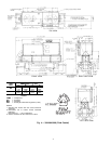
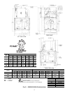
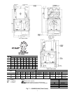
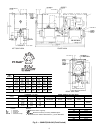
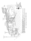
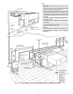
devices. Locate unit indoors. See Fig. 4-8 for unit dimen-
sional details.
Allow 36 in. (914 mm) in front of the unit for control box
access door. Compressor can be removed from either side or
the front of the unit. Prior to installation determine which
direction compressor will be removed, and leave 3 to 4 ft
(914 to 1219 mm) clearance for removal.
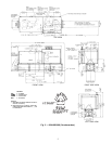
On 30HK,HL units leave 7
1
⁄
2
ft (2.3 m) (for 040 units) or
9 ft (2.7 m) (for 050,060 units) clearance on one side for
cooler tube removal. Leave 2 ft (610 mm) clearance on the
other side for making fluid connections to cooler and water
connections to condenser. See Fig. 4 and 5.
On 30HWA,B units, leave 2 ft (610 mm) on one side for
making fluid connections to cooler and water connections to
condenser, accessing the thermostatic expansion valve (TXV),
and replacing heat exchanger(s) if necessary. See Fig. 6
and 7.
On 30HWC,S units, leave 75 in. (1905 mm) on one side
for condenser tube removal and 2 ft (610 mm) on the other
side for making fluid connections to cooler and water con-
nections to condenser, accessing the TXV, and replacing heat
exchanger(s) if necessary. See Fig. 8.
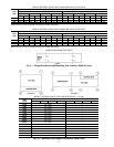
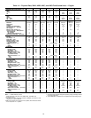
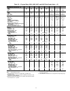
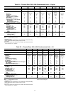
The floor must be strong enough to support the unit op-
erating weight (see Tables 1A-2B and Fig. 9 and 10). If nec-
essary, add a supporting structure (steel beams or reinforced
concrete slabs) to the floor to transfer weight to nearest beams.
Additional weights of factory-installed options (30HW only)
are:
Sound enclosure — 75 lb (34 kg)
Hot gas bypass — 15 lb (7 kg)
80-amp non-fused disconnect — 15 lb (6.8 kg)
100-amp non-fused disconnect — 25 lb (11.3 kg)
200-amp non-fused disconnect — 70 lb (31.8 kg)
Be sure interconnecting piping and electrical conduits
are suspended freely, and are not in contact with any
adjacent walls. Be sure unit capillaries are not rubbing
against anything.
Step 1 — Inspect Shipment — Inspect unit for dam-
age or missing parts. If damaged, or if shipment is incom-
plete, file a claim immediately with the shipping company.
Step 2 — Rig and Place Unit
30HK,HL UNITS — On each end of cooler, a steel loop is
provided for the preferred method of lifting unit. Use spreader
bars to keep cables away from compressor enclosure and
control box. If unit is to be moved by forklift truck, use one
of the following two methods:
1. From front or rear, lift under the cooler rails. Unit can be
either on or off skid.
2. When moving from the ends, leave unit on the skid. Lift
from under the skid.
If unit is to be dragged into final position, or moved on
rollers, it is recommended that it be left on the skid. When
dragging or rolling, apply force only to the skid, not to the
unit. Lift from above, using the lifting angles provided, to
remove unit from the skid.
30HW UNITS
NOTE: If accessory mobility package (Carrier part no.
30HW900008) is to be used, install this accessory after bring-
ing unit into building and before moving the unit to its final
location per installation instructions provided with the
accessory.
Units Equipped With Factory-Installed Unit Wheels — This
factory-installed option consists of 4 swivel-type wheels
mounted to the legs of the unit. See Fig. 11. For units equipped
with this option, leave the skid on until the unit is in the
building. Once in the building, remove the skid, and wheel
the unit to its final location.
NOTE: The wheels are equipped with a thumb-screw brake.
Units Not Equipped With Factory-Installed Unit Wheels —
Do not remove the skid until the unit has been moved to its
final location. The unit may be moved by means of rollers
under the skid, a forklift truck, or rig and slings.
Step 3 — Place the Unit
30HK,HL UNITS — When unit is in final position, remove
skid, level the unit (using a level), and bolt the unit to floor
or pad.
NOTE: These units are not suitable for unprotected outdoor
use.
Carrier recommends that these units be located in the base-
ment or on the ground floor. However, if it is necessary to
locate the unit on an upper floor, be sure the structure has
been designed to support the unit weight. If necessary, add
structural support to floor. Also, be sure the surface for in-
stallation is level. Refer to Fig. 4 and 5 for space require-
ments and Fig. 9 for weight distribution.
Only electrical power connections, water connections for
condenser, and fluid connections for cooler are required for
30HK installation. Installation of 30HL units varies only in
field piping required for the remote condenser.
30HW UNITS — When the unit is in its final position, re-
move the skid (from units not equipped with factory-
mounted wheels), or remove the wheels (if equipped). Re-
move
3
⁄
8
-in. wheel nuts to remove wheels from unit legs.
Level the unit (using a level), and bolt the unit to the floor
or pad.
If unit is to be mounted on unit external vibration isola-
tors, follow the mounting instructions included with the ac-
cessory vibration isolator (Carrier part numbers 30HW900-
001 and -002).
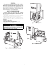
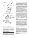
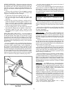
Step 4 — Check Compressor Mounting and
Connections —
As shipped, the compressor is held down
by special self-locking nuts (Fig. 12). After unit is installed,
loosen the self-locking nuts one at a time until compressor
floats freely. Do not remove nuts, as they are self-locking
and will hold their locked position.
3