


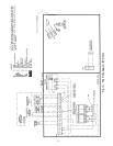
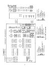

Step 6 — Make Electrical Connections — All field
wiring must comply with local code requirements. Electrical
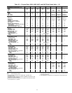
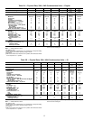
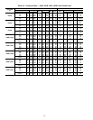
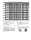
data for the complete unit and for the compressors is shown
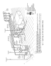
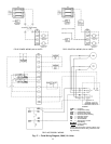
in Tables 4A and 4B. See Fig. 17 and 18 for field wiring
connections.A field-supplied branch circuit disconnect switch
that can be locked in either OPEN or OFF position must be
installed.
30HK, HL UNITS — On all 60 Hz units, a fused (15 amp
maximum), 115 v control circuit must be supplied by either
a separate power source or by using a minimum 300 va trans-
former. On 208/230 and 460 v units, control circuit power
can be supplied by accessory transformer part no. 07EA900051.
Check to be sure that installation of the 115 v control power
source meets all local codes.
On all 50 Hz units, a fused (15 amp maximum), 230 v
control circuit must be field supplied. On 200-3-50 units, power
for the control circuit can be supplied by connecting a field-
supplied fuse (15 amp maximum) between TB1 and TB2 for
L1 overcurrent protection. On 400-3-50 units, power for the
control circuit can be supplied by connecting a field-
supplied fuse (15 amp maximum) between TB1 and a neu-
tral leg from TB2 for L1 overcurrent protection. On all units,
check to be sure that installation of the 230 v control power
source meets all local codes.
30HW UNITS — Control circuit power is 24 v and 115 v
on all units, and is supplied by factory-installed control
transformers.
ALL UNITS — Inside the control box are terminals for field
power and ground (earth) wiring, as well as a terminal for a
neutral wire when needed (380-3-60 and 400-3-50 units only).
A ground wire must be installed with each field power sup-
ply. Compressor are wired standard from the factory for across-
the-line start.As a factory-installed option, all 025-060 sizes
are available wired for part-wind start (special order option
on 30HK, HL unit).
Refer to Tables 4A and 4B for electrical data.
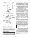
Flow Switch — Acooler flow switch is required for all units,
and must be field-installed. The Carrier flow switch acces-
sory (part number 30HW900003), is available for this pur-
pose. Flow switch wiring terminals are located in the field
wiring compartment of the control box. The flow switch should
be wired between terminals TB3-1 and TB3-7 for 30HK, HL
units or between terminals TB2-7 and TB2-13 for 30HW units.
The factory jumper wire between these 2 terminals must be
removed for proper operation of the flow switch.
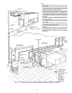
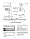
Control Box, Power Section — The electrical power supply
is brought in through the top left-hand side (30HK, HL) or
right-hand side (30HW) of the control box (see Fig. 19 and
20). The knockout accepts up to a 3-in. (76 mm) conduit for
30HK, HL units, and a 1
3
⁄
4
-to2
1
⁄
2
-in. (44 to 64 mm) conduit
for 30HW units. Pressure-lug connections on the terminal
blocks are suitable for copper, copper-clad aluminum, or alu-
minum conductors.
The control box power section contains the following
components:
• power terminal block
• compressor circuit breaker(s)
• compressor contactor(s)
• high-voltage transformer (30HW units only)
• control-circuit circuit breaker for 24-v circuit
• unit ON-OFF switch
• unit service light
• ground lug
• neutral terminal (380-3-60 and 400-3-50 units)
• terminal block for ground current sensing accessory
Control Box, Controls Section — The control box controls
section contains the following components:
• temperature controller
• control relay(s)
• control module(s)
• low-voltage control transformer(s)
• terminal block for ground current sensing accessory
Control Box, Field Control Wiring Section — Inside this
section is a 10-terminal (30HK, HL) or 14-terminal (30HW),
low-voltage, field-wiring terminal strip.All low-voltage field-
wiring connections are made to this terminal block. Seven
3
⁄
4
-in. (19 mm) knockouts are provided for field wiring in
this section. Connections for chilled fluid flow switch, chilled
fluid pump interlock, condenser pump interlock, remote alarm
output, and ground current sensor accessory are made at this
location. The remote condenser relay connections are made
to a separate 4-terminal (30HK, HL) or 3-terminal (30HW)
field wiring strip. See Fig. 17-20 for specific location of
connections.
Unbalanced 3-Phase Supply Voltage — Never operate a com-
pressor where a phase imbalance in the supply voltage is
greater than 2%. Use the following formula to determine
the percent voltage imbalance:
% Voltage Imbalance =
max voltage deviation from average voltage
100 x
average voltage
Example: Supply voltage is 240-3-60
AB = 243 v
BC = 236 v
AC = 238 v
243 + 236 + 238
Average Voltage =
3
= 239 v
Determine maximum deviation from average voltage:
(AB) 243 - 239=4v
(BC) 239 - 236=3v
(AC) 239 - 238=1v
Maximum deviation is 4 v.
Determine percent voltage imbalance:
4
% Voltage Imbalance = 100 x
239
= 1.7%
This amount of phase imbalance is satisfactory as it is below
the maximum allowable 2%.
IMPORTANT: If the supply voltage phase imbalance
is more than 2%, contact your local utility company
immediately.
19