


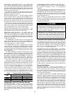
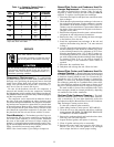
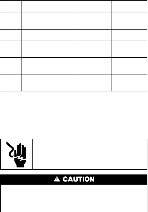
Table 11 — Capacity Control Steps —
30HW Standard Units
UNIT CAPACITY CONTROL CAPACITY OPERATING
30HW STEPS* % CYLINDERS
018
1 33.3 2
2 66.7 4
3 100.0 6
025
1 50.0 2
2 100.0 4
028
1 33.3 2
2 66.7 4
3 100.0 6
035
1 33.3 2
2 66.7 4
3 100.0 6
040
1 33.3 2
2 66.7 4
3 100.0 6
*Factory-installed hot gas bypass option adds an additional capacity
step to that shown in this table.
SERVICE
ELECTRIC SHOCK HAZARD
To avoid the possibility of electrical shock,
turn off all power to unit before servicing.
Do not attempt to bypass, short-out, or modify the con-
trol circuit or electronic boards in any way to correct a
problem. This could result in component failures or a
hazardous operating condition.
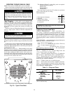
Compressor Replacement — If a replacement
6-cylinder compressor has a center-bank cylinder head with
discharge valve pad facing the pump end, remove head and
install reverse flange head from original compressor (dis-
charge valve pad toward the motor end). Center-bank cyl-
inder head cannot be rotated 180 degrees.
Be sure all the hardware from the old compressor is
removed and installed on the new compressor, including
the high-pressure switch snubber, the discharge gas thermo-
stat (30HW025-040), the oil pressuresafety switch (if equipped),
and the low-pressure switch.
The compressor can be removed from either the front or
the sides of the unit, depending on where clearance space
was allowed during unit installation.The compressor and mount-
ing hardware are mounted on a plate which is screwed down
to the unit basepan. Remove the 4 screws holding the plate
to the basepan and the plate should easily slide out of the
unit. Mount the replacement compressor to the plate, slide
the plate back into the unit and secure with the 4 screws.
Circuit Breaker(s) — The breaker(s) provides 3-leg over-
load protection. Do not bypass connections or increase the
size of the circuit breaker(s) to correct trouble. Determine
the cause of the trouble and correct it before resetting the
breaker(s).A tripped breaker must be manually reset by mov-
ing the circuit breaker handle to OFF, then ON position. See
Tables 4A and 4B for must-trip amps (MTA).
NOTE: One circuit breaker is provided per compressor.
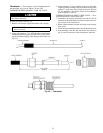
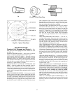
Brazed-Plate Cooler and Condenser Heat Ex-
changer Replacement —
Brazed-plate heat exchang-
ers cannot be repaired if they develop a leak. If a leak (re-
frigerant or water) develops, the heat exchanger must be
replaced. To replace a brazed plate heat exchanger:
1. Disconnect the liquid-in and liquid-out connections at the
heat exchanger.
2. Check that the replacement heat exchanger is the same as
the original heat exchanger. For the condensers, compare
part numbers on the heat exchangers. For the coolers, in-
sulation covers the manufacturer’s part number. Make sure
the depths of the replacement and original cooler heat ex-
changers are the same.
3. Reclaim the refrigerant from the system, and unsolder the
refrigerant-in and refrigerant-out connections.
4. Remove the four
1
⁄
2
-in. nuts holding the heat exchanger
to the brackets. Save the nuts.
5. Install the replacement heat exchanger in the unit and
attach to the bracket using the four
1
⁄
2
-in. nuts removed
in Step 4.
6. Carefully braze the refrigerant lines to the connections on
the heat exchanger. Lines should be soldered using silver
as the soldering material with a minimum of 45% silver.
Keep the temperature below 1472 F (800 C) under nor-
mal soldering conditions (no vacuum) to prevent the cop-
per solder of the brazed plate heat exchanger from changing
its structure. Failure to do so can result in internal or
external leakage at the connections which cannot be
repaired.
7. Reconnect the water/brine lines.
8. Dehydrate and recharge the unit. Check for leaks.
Brazed-Plate Cooler and Condenser Heat Ex-
changer Cleaning —
Brazed-plate heat exchangers must
be cleaned chemically.Aprofessional cleaning service skilled
in chemical cleaning should be used. Use a weak acid (5%
phosphoric acid, or if the heat exchanger is cleaned fre-
quently, 5% oxalic acid). Pump the cleaning solution through
the exchanger, preferably in a backflush mode. After clean-
ing, rinse with large amounts of fresh water to dispose of all
the acid. Cleaning materials must be disposed of properly.
The mesh screens in front of the water/brine inlets of the
heat exchangers should be cleaned periodically, depending
on condition of the chiller water/brine.
Shell-and-Tube Condenser Cleaning — The shell-
and-tube condenser tubes can be cleaned either mechani-
cally or chemically. To clean them chemically, follow the
procedure described in Brazed-Plate Cooler and Condenser
Heat Exchanger Cleaning section above.
To clean the condenser tubes manually:
1. Order tubing brushes (Carrier part no. KC21AH105).
2. Close the valves on the condenser and relieve condenser
water pressure. BE SURE TO PROVIDE DRAINAGE
TO PREVENT WATER DAMAGE.
3. Remove the condenser heads and brush the tubes clean,
removing scale and other deposits.
4. Inspect the head gaskets and replace if necessary.
5. Clean all gasket surfaces prior to reassembly.
6. Replace the water heads and torque the head bolts to
90 ft-lb (122 N-m). Allow the gaskets to set overnight
and re-torque the bolts to ensure proper sealing.
32