


PRE-START-UP
IMPORTANT: Before beginning Start-Up, complete
Start-Up Checklist on pages CL-1 to CL-4. This check-
list assures proper start-up of a unit, and provides a
record of unit condition, application requirements, sys-
tem information, and operation at initial start-up.
ELECTRIC SHOCK HAZARD
Open all disconnects before servicing this
equipment. There may be more than one
disconnect.
Initial Check
IMPORTANT: Electrical power source must agree
with unit nameplate rating. Do not start the chiller, even
momentarily, until the following checks have been
completed.
1. Check all auxiliary components, such as cooling tower
(if used), chilled liquid and condenser water pumps, air-
handling equipment, or other equipment to which
the chiller supplies liquid. Consult manufacturer’s
instructions.
2. Be sure flow switch is properly installed and set. See
instructions packaged with flow switch accessory.
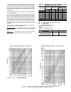
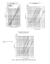
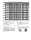
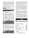
3. Set the temperature controller deadband as specified in
Tables 5 and 6. Set point should be at the desired cooler
leaving fluid temperature. Refer to Chilled Fluid Tem-
perature Controller section on page 29 for additional dead-
band setting information.
4. Backseat (open) compressor suction and discharge shut-
off valves. Crack open valves (one turn in) to allow some
pressure to each test gage (if installed).
5. Backseat (open) liquid line shutoff valve(s).
6. Open valve to capillaries from fluid regulating valve (when
used).
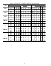
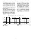
7. Fill chilled fluid liquid circuit with clean water or other
noncorrosive fluid to be cooled. Bleed all air out of the
high points of the system. Set flow rate according to job
requirements. See Table 3. If the chilled water is to be
maintained at a temperature below 40 F (4.4 C), a brine
of sufficient concentration must be usedto prevent freeze-up
at anticipated suction temperatures.
8. Open supply valve (or fill cooling tower, if used) for
condenser water.
9. Check tightness of all electrical connections.
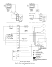
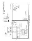
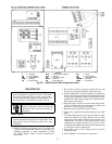
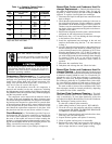
LEGEND
C—Contactor
CB — Circuit Breaker
CM — Control Module
COM — Common
CR — Control Relay
SW — Switch
TB — Terminal Block
TDR — Time Delay Relay
THERM — Termistor
TRAN — Transformer
GCS — Ground Current Sensor
GND — Ground
NC — Normally Closed
NEUT — Neutral
NO — Normally Open
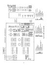
Fig. 20 — 30HW Control Box Components Label
25