


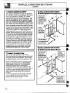
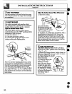

mLEVELBMGTHEmGE
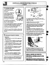
1. Removethe storage
drawer,broilerdraweror
kickpanel.
2. Usea 3/l& open-endor
socketwrenchtobackout
bothrearlevelinglegs
approximatelytwoturns.
3. Usea 1%”open-endor
adjustablewrenchto back
outthefrontlevelinglegs
twoturns.
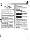
4. Installthe ovenshelvesin
the ovenandpositiontherange
whereitwillbe installed.
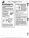
5. Checkforlevelnessbyplacinga spiritlevelor
a cup,partiallyfilledwithwater,on oneofthe
ovenracks.Husinga spiritlevel,taketwo
readings-with the levelplaceddiagondlytist
inonedirectionandthenthe other.
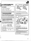
6. Adjustthelevelinglegsuntiltherangeislevel.
7. Afterthe rangeis level,slidethe rangeaway
fromthewallsothatthe Anti-Tipdevicecanbe
installed.
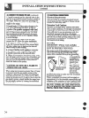
m BHSTALLIHGTHEMTU=TIPDEWHCE
W~ING:
~Rangemustbe securedwithanapproved
Anti-Tipdevice.
@Unlessproperlyinstiled, the rangecould
be tippedbyyouor a childstanding,sitting
or leaningonan opendoor.
@Mer instiling theAnti-Tipdevice,verify
thatit is inplaceby carefullyattemptingto
tiltthe rangeforward.
~Thisrangehas beendesignedtomeet all
recognizedindustrytipstandardsforall
normalconditions.
~The use ofthis devicedoesnotpreclude
tippingofthe rangewhennot properly
installed.
~IftheAnti-Tipdevicesuppfiedwiththe
rangedoesnotfitthis application,use the
universalAnti-Tipdevice~02X7909.
,
*
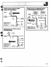
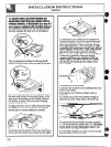
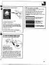
1. MarkthewallwheretheMGHTEDGEofthe
rangeistobe located.Besuretoallowforthe
countertopoverhangtiyouintendtoinstallthe
rangenexttocabinets.
40
Anti-Tip
Device
i
i
Slotted
I
Head
-----i--
Screw Wallplatf3I
Approx,~~”’
I
9-’
I
,/
2%
II
~’ tvlarkedEdge
/
./
ofRange
,#~
2. Locatetheoutsideedgeofthe device2Y
towardthecenteroftherangefromthemarked
edgeoftherange.
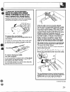
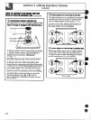
3.
U@ngthe deviceas a template,markthe
positionofthe holeforthe screw.
4. Forwoodconstruction,drilla pilotholeat an
angleof20degreesfromthe horizontal.Anail
or awlmaybe usedifa drillisnotavailable.
MounttheAnti-Tipdevicewiththe screw
provided.
Forcementorconcreteconstruction,you
willneeda I/&x 1%”lagboltanda 1/2”O.D.
sleeveanchor,whichare notprovided.Drill
the recommendedsizeholeforthe hardware.
Instil the sleeveanchorintothe drilledhole
andthen installthe lagboltthroughtie device.
The boltsmustbe properlytightenedas
recommended-forthe hardware.
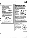
Backof
Range
5. Stidethe rangeagainstthe wall,andcheck
forproperinstallationbygraspingthe tiont
edgesofthe rear surfaceunitopeningsand
carefullyattemptingto tiltthe rangeforward.
m
m
e