


CSL
CSM
CSB
64
ELECTRICAL SUPPLY
Standard electrical supply for all Combi-Steamers is 208-240 volt, 3 phase, 50-60 Hz.
NOTE: The power connections are located behind the service door (see section 5-3).
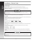
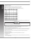
Each unit requires a separate fused service according to the following table: (3 phase only)
Model Voltage Phase Amps Load
CSL/M/B-6 208V 3 27 9.6KW
CSL/M/B-6 208V 1 46 9.6KW
CSL/M/B-6 240V 3 27 9.6KW
CSL/M/B-6 240V 1 40 9.6KW
CSL/M/B-10 208V 3 52 18.6KW
CSL/M/B-10 240V 3 45 18.6KW
CSL/M/B-1020 208V 3 88 31.5KW
CSL/M/B-1020 240V 3 76 31.5KW
CSL/M/B-20 208V 3 103 37.2KW
CSL/M/B-20 240V 3 90 37.2KW
CSL/M/B-40 208V 3 175 63KW
CSL/M/B-40 240V 3 152 63KW
NOTE: When the oven is installed it must be electrically grounded in accordance with local codes, or in the absence of local
codes, with the National Electric Code, ANSI/NFPA 70-1990.
NOTE: All connections must comply with the oven data plate. A separate fused disconnect switch or circuit breaker
(not furnished) MUST be installed in the electrical supply line FOR EACH OVEN!
NOTE: The electrical diagram is located behind the service door.
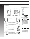
The electric supply terminal block, located behind the service door, is clipped on a mounting rail which is attached to the
frame of the unit. The three phases of the power cord are connected to the three gray colored terminals. Ground is con-
nected to the yellow-green terminal.
NOTE: The phase sequence does not have to be observed because of the automatic reversing action of the fan motor.
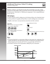
CHANGES IN VOLTAGE
To change voltages of the Combi-Steamers (ex: 208 to 240 volt) the following has to be changed:
1) Air and steam elements
2) Contactor LS5
3) CSM and CSL units - the wires on the control panel transformer and the interior light transformer must be switched to
the correct voltage terminals.
Do Not use conduit as a supply ground, or electrical shock could result.