


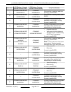

ELECTRICAL OPERATION
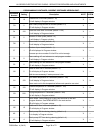
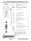
COMPONENT FUNCTION
Power Switch ......... Controls power to control circuits.
High Limit Thermostat ...Prevents oven from exceeding 482°F ±12 °F if controls malfunction.
Wash Pump M1
(KA7E) ................
Circulates water and detergent during wash cycle.
Drain Pump M2 ....... Empties water from oven when turned on.
Rotisserie Motor M3 ... Turns the rotisserie.
Blower Motors M4, M5 ...Circulates air inside oven cavity.
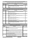
Grey Water/Sump
Pump M6 (KA7E) .....
Empties remaining water from sump area. Removed from ovens with Serial No.
46300096 and higher
Grease Pump M7 ..... Empties grease accumulated in sump prior to wash cycle. KA7EM models with grease
assist only.
Chemical Pump M8
(KA7E) ................
Dispenses predetermined amount of detergent for wash cycle.
Water Fill Valve S1
(KA7E) ................
Is turned on to fill oven with fresh water for wash and rinse cycles.
Water Level Control
Board (KA7E) .........
Monitors input from water level sensor and chemical sensor.
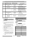
CPU Board ............ Allows input from keypad, controls oven functions.
Contactor K1 ......... Power to oven heat elements. Controlled by CPU board.
Contactor K2 ......... Supplies power to oven heat elements and controlled by power switch and by high limit
thermostat.
Relay K3 (KA7E) ...... Monitors door interlock switches and provides power to wash pump.
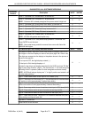
Light (internal) ........ Provides light for inside oven.
Temperature Sensor ... Senses temperature of oven cavity for the CPU control.
Display Board ........ Shows time and temperature; also contains keypad for programming CPU board.
Rotisserie Motor
Capacitor C1 ..........
Start capacitor for rotisserie motor.
Blower Motor
Capacitors C2, C3 ....
Run capacitors for blower motors M2, M3.
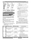
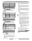
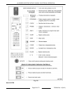
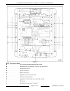
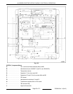
SEQUENCE OF OPERATION
Refer to Model KA7E Schematic Sheet 1 and Sheet 2
for the electrical sequence of operation. The letter "P"
followed by a 2 digit number refers to the Program
Item Number in SERVICE MODE - PROGRAMMING
AND DIAGNOSTICS.
Programmed Cooking
1. Conditions
A. Oven connected to correct supply voltage
and is properly grounded.
B. Control board is powered and LED on board
is flashing to indicate power is applied.
NOTE: Control board is powered and neutral is
applied to the oven component circuitry when supply
voltage is connected to the oven. The power switch
controls power for the oven to operate, not power to
the oven.
C. Power switch is off.
KA SERIES ELECTRIC ROTARY OVENS - ELECTRICAL OPERATION
F25294 Rev. A (0412) Page 46 of 72