


27
Model H63 Operat ing Procedures
090130
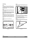
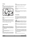
Rinsing
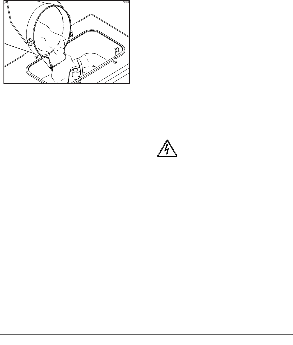
Step 1
Pour two gallons (7.6 liters) of cool, clean water i nto
the mix hopper . With the brushes pr ovided, scrub the
mix hopper, mix level sensing probes, the outside of
the agitator housing, and the mix inlet hole.
Figure 30
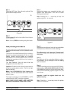
Step 2
With a mix pail beneath the door spout, press the
WASH key.
Step 3
Open the draw valve on the freezer door. Drain all the
rinse water from the door spout, close the draw valve,
and press the WASH key cancelling the wash cycle.
Repeat this procedure until the rinse water being
drawn from the f reezing c ylinder is clear.
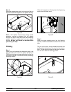
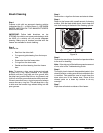
Hopper Cleaning
Step 1
Prepare a pail o f an approved 100 PPM cleaning solu-
tion (examples: 2--1/2 gal. [9.5 liters] of Kay--5R or
2 gal. [7.6 liters ] of Stera--SheenR). USE WARM WA-
TER AND FO LLOW THE MANUFACTURER’S
SPECIFICATIONS.
Step 2
Pour the c leaning solution into the hopper and allow it
to flow into the freezing cylinder.
Step 3
While t he solution is flowing into the freezing cylinder ,
brush clean the mix hopper, mix level sensing probes,
the outside of t he agitator housing, and mix inlet hole.
Step 4
Press the WASH key and allow the c leaning solution
in the fr eezing cylinder to agitate for f ive minutes.
Step 5
Place an empty pail beneat h the door spout.
Step 6
Open t he draw valve on the freezer door and draw off
all the solution.
Step 7
Once the cleaner stops flowing fr om the door spout,
close the draw valve and press the WASH key
cancelling wash cycle.
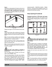
Disassembly
Note: Failure to r emove par ts, brush c lean and then
air dry these parts , will result in dam age to the related
parts. These parts must be removed every 14 days or
the mac hine will lock--out and will not operate in the
AUTO mode.
BE SURE THE CONTROL SWITCH IS IN
THE OFF POSITION. Failure to do so may cause
injury from electrocution or hazardous moving parts.
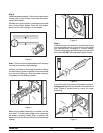
Step 1
Lift out the torque arm. Disengage the draw arm f rom
the draw valv e bracket and rotate the bracket to the
right.
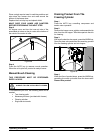
Step 2
Remove the handscrews , freezer door, torque roto r
assembly, beater , scraper blades, and drive shaftfr om
the freezing cylinder. Take these parts to t he s ink for
cleaning.
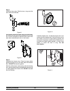
Hint : If the guide bearing is not connect ed to the end
of the torque rotor shaft, it is still lodged in the beater
drive shaft. To remove the guide bearing, insert the
torque arm into the side hole of the drive shaft and
push the bearing forward.
Step 3
Remove the front drip tr ay and splash shield.