12
Models H62 & H63Important: To the Operator
120206
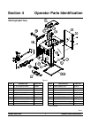
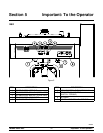
H63
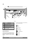
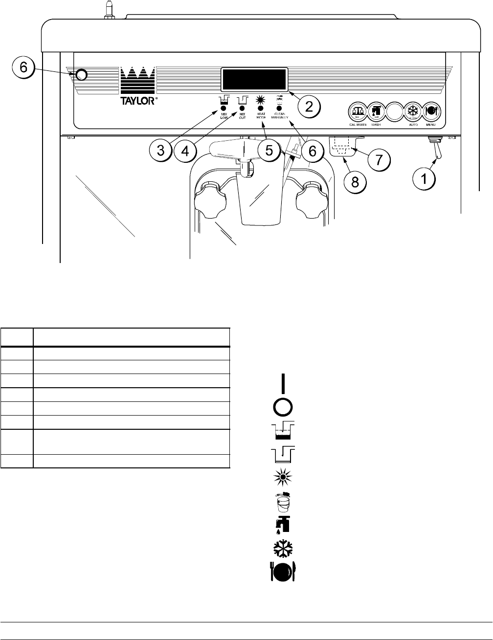
Figure 6
ITEM
DESCRIPTION
1 POWER SWITCH (TOGGLE)
2 LIQUID CRYSTAL DISPLAY
3 LED INDICATOR--MIX LOW (PCB A--LED)
4 LED INDICATOR--MIX OUT (PCB A--LED)
5 LED INDICATOR--HEAT MODE
6 LED INDICATOR--CLEAN MANUALLY
7 CO NSISTENCY CONTROL
(SWITCH--TORQUE)
8 COVER--VISCOSITY ADJUSTMENT
Symbol Definitions
To better communicate in the International arena, the
words on many of our operator switches and buttons
have symbols to indicate their functions. Your Taylor
equipment is designed with these International
symbols.
The following chart identifies the symbol definitions
used on the operator switches.
=ON
=OFF
=MIXLOW
= MIX OUT
=HEATMODE
= CLEAN MANUALLY
= WASH
=AUTO
=MENU


