23
Models H62 & H63 Operating Procedures
111012
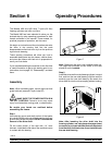
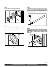
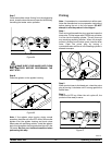
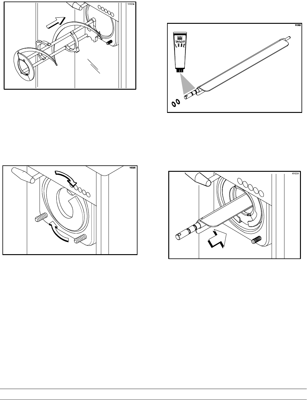
Step 3
Slide the beater into the freezing cylinder.
Figure 9
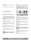
Step 4
Make sure the beater assembly is in position over the
drive shaft. Turn the beater slightly to be certain that
the beater is properly seated. When in position, the
beater will not protrude beyond the front of the freezing
cylinder.
Figure 10
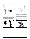
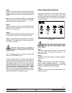
Step 5
Assemble the torque rotor by s lidingthe two o--rings on
the front of the shaft and lubricate them thoroughly to
prevent leaking. Place the white plastic guide bearing
on the rear of the rotor shaft. DO NOT lubricate the
plastic guide bearing.
Figure 11
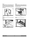
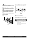
Step 6
Insert the torque rotor , plastic guide bearing end first,
making sure that it fits into the hole in the beater drive
shaft. Rotate it several times to check for proper
positioning.
Figure 12


