


11
Installation and Set-Up
Machine Set-Up
Receiving And Handling
After the machine has been uncrated, examine the case sealer for damage that might have occurred during
transit. If damage is evident, file a damage claim immediately with the transportation company and also
notify your 3M Representative.
It is recommended that the case sealer be set-up and operated with product before placing it in the production
line. This approach will allow your thorough review and familiarization with the 800af before subjecting it and
operating personnel to a production situation where time for set-up, adjustments, and operator training usually
becomes limited.
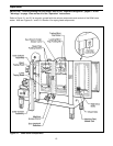
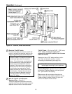
The following instructions are presented in the order recommended for setting up and installing the case sealer.
Following them step by step will result in an installation in your production line that best utilizes the many features
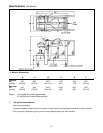
built into the case sealer. Refer to Figure 3-1 and 3-2 to identify the various components and controls of the
machine.
IMPORTANT – Read "Warnings" on page 18 before attempting to set-up the case sealer for operation.
For future reference, record machine serial number on front cover of this instruction manual in the space
provided.
1. Follow "Unpacking Instructions" label attached to corrugated packing cover.
2. Use appropriate material handling equipment to remove the machine from the pallet and move it into position.
Whenever the machine is lifted with a fork truck, insure that the forks span completely across the machine
frame and do not contact any wiring or mechanism under the machine frame. In some cases the lower taping
head may need to be removed to avoid damage.
CAUTION – Machine weighs approximately 370 kg [820 lbs] uncrated.
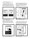
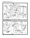
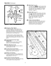
2. Remove and discard cable ties on upper head assembly.
3. Install the crank handle on the top of the left column, as shown in Figure 2-1A.
4. Install upper tape drum bracket on the top cross bar, as shown in Figure 2-1B.
5. Install the two infeed end guards. Attach the guards to the infeed end vertical masts, as shown in
Figure 2-1C.
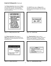
6. Raise upper head assembly (turn crank handle counterclockwise). Install the machine stops (from parts bag).
Mount these stops as shown in Figure 2-1D using lowest hole position on brackets. The upper hole position
in the stops should only be used when the heads are adjusted to apply 50 mm [2 inch] tape legs.
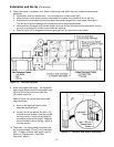
7. The lower tape drum bracket assembly is mounted on the lower head in the standard position. Ensure that
the bracket assembly is mounted straight down, as shown in Figure 2-2A. The tape drum bracket assembly
can be pivoted to provide clearance or for retrofit in certain cases.
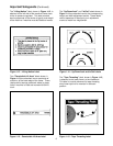
Lower outboard tape roll mounting (alternate position) –
a. Remove lower taping head from machine.
b. Remove existing tape drum bracket from taping head and replace with bracket/roller assembly (shipped
loose), Figure 2-2B. Replace taping head in machine.
c. Install tape drum bracket (removed from taping head) on exit end of machine lower frame as shown in
Figure 2-2B.