


29
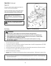
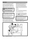
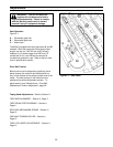
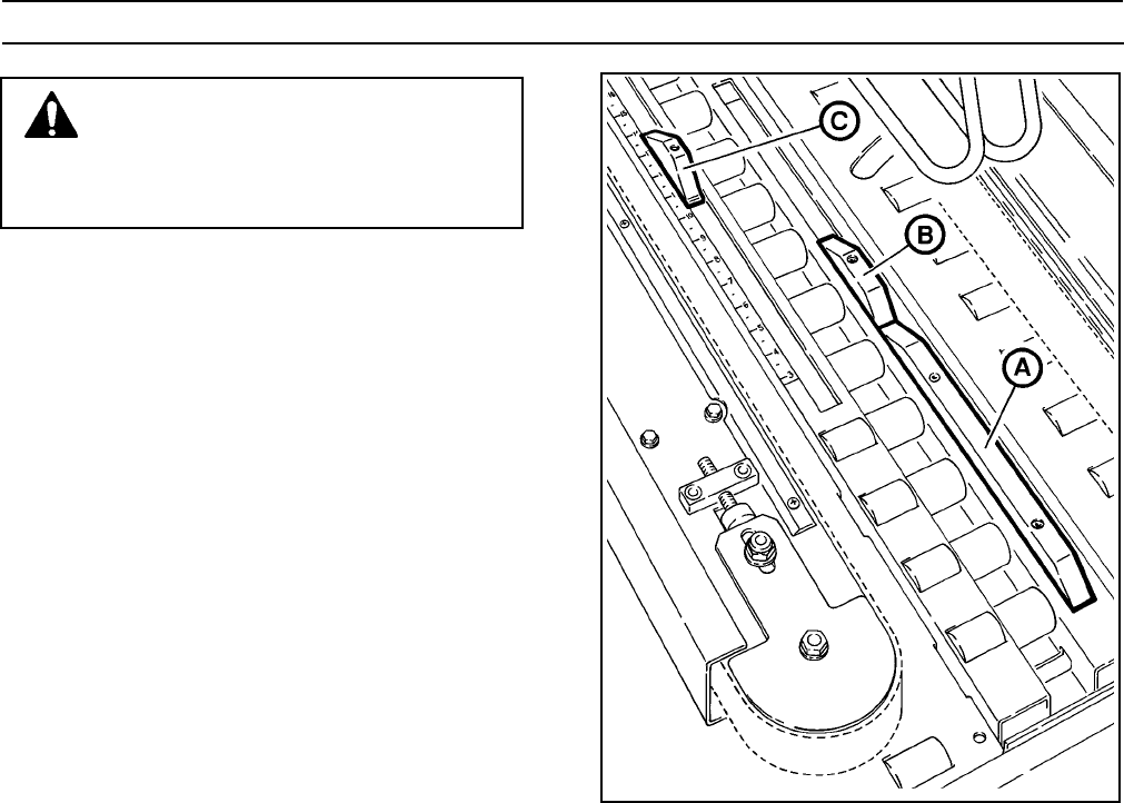
Figure 5-1 – Gate Cams
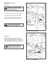
Adjustments
WARNING – Turn air and electrical
supplies off and disconnect before
beginning adjustments. Failure to comply
with this warning could result in severe
personal injury or equipment damage.
Gate Operation
Figure 5-1
A – Permanent gate cam
B – Removable gate cam
C – Kicker cam
The 800af is shipped with both gate cams A and B
installed. With both cams the entire range of box
lengths can be run (150-760 mm [6-30 inches]).
However if only boxes longer than 305 mm [12
inches] will be run, cam B can be removed to
increase the production rate. Refer to the box rate
chart in specification section.
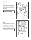
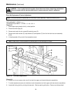
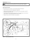
Drive Belt Tension
Belt tension must be adequate to positively move
boxes through the machine and belts should run
fully on the surface of the pulleys at each end of the
frame. The idler pulleys on the infeed end are
positioned by tension adjustment screws. To
adjust tension, see "Maintenance – Drive Belt
Replacement/Tension Adjustment", page 26.
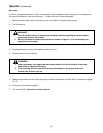
Taping Head Adjustments – Refer to Section II
TAPE WEB ALIGNMENT – Section II, Page 11
TAPE DRUM FRICTION BRAKE – Section II,
Page 11
APPLYING MECHANISM SPRING – Section II,
Page 12
ONE-WAY TENSION ROLLER – Section II,
Page 12
TAPE LEG LENGTH ADJUSTMENT – Section II.
Page 13