


23
List of Figures
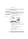
Figure 1-1 The Attenuator Keys ................................................................................ 29
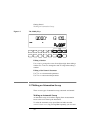
Figure 1-2 The Modify Keys ..................................................................................... 30
Figure 1-3 The Parameters for an Automatic Sweep ................................................. 31
Figure 1-4 The Hardware Configuration for the Back Reflector (Options 201 and 203) 32
Figure 2-1 The Hardware Configuration for the Attenuator ...................................... 37
Figure 2-2 The Attenuation Factor on the Display .................................................... 38
Figure 2-3 The Calibration Factor on the Display ..................................................... 39
Figure 2-4 The Wavelength on the Display ............................................................... 41
Figure 2-5 Hardware Configuration for Attenuation Example - A ........................... 42
Figure 2-6 Hardware Configuration for Attenuation Example - B ............................ 43
Figure 3-1 The Hardware Configuration for the Attenuator ...................................... 47
Figure 3-2 The Parameters for an Automatic Sweep ................................................. 49
Figure 3-3 Selecting the Automatic Sweep Application ........................................... 49
Figure 3-4 Running the Automatic Sweep ................................................................ 51
Figure 3-5 Editing the STOP Parameter .................................................................... 52
Figure 3-6 Running the Manual Sweep ..................................................................... 53
Figure 4-1 The Hardware Configuration for the Back Reflector ............................... 59
Figure 4-2 Editing the Value for the Reference Return Loss .................................... 61
Figure 4-3 Executing the Back Reflector Application ............................................... 62
Figure 4-4 Hardware Configuration for Variable Return Loss .................................. 63
Figure 5-1 The LAMBDCAL Indicator on the Display ................................................ 68
Figure 5-2 The USERCAL Indicator on the Display .................................................. 69
Figure 5-3 The Display in Through-Power Mode ..................................................... 70
Figure 6-1 The Display when Recalling the Default Setting ..................................... 77
Figure 8-1 Common Status Registers ........................................................................ 94
Figure 8-2 The Status Registers ................................................................................. 116
Figure 9-1 Hardware Configuration for Attenuation Example - A ........................... 135
Figure 9-2 Hardware Configuration for Attenuation Example - B ............................ 136
Figure A-1 Line Power Cables - Plug Identification ................................................. 144
Figure A-2 Rear Panel Markings ............................................................................... 145
Figure A-3 Releasing the Fuse Holder ...................................................................... 147
Figure A-4 The Fuse Holder ...................................................................................... 147
Figure A-5 Correct Positioning of the Attenuator ..................................................... 149
Figure A-6 GPIB Connector ...................................................................................... 151
Figure B-1 Straight Contact Connector Configuration .............................................. 159