


24 __________________________________________________________Barco - DCMS - User Manual
Connecting the components
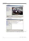
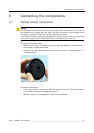
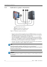
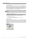
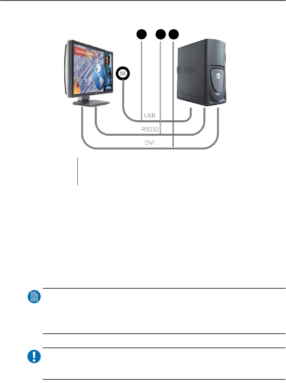
5.2 Calibration system connection
Figure 4: Calibration system connection
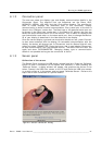
• Plug the sensor (delivered together with the DCMS software) in one of the
USB connections of your PC. See also ‘Optical sensor connection’ paragraph.
The USB color sensor measures color and luminance.
• Connect the display to be calibrated to the PC by using the correct RS232
cable. The RS232 is used to control the display and to upload the calibration
parameters. The RS232 can also be used to set RGB test patterns in stead of
DVI or when no DVI connection to the monitor is available.
• Connect a DVI cable (not delivered) between PC and display to be calibrated.
The DVI connection is used to display color patches.
NOTE
:
If the display is already connected to a different DVI source, the serial connection can be used
to control the display’s internal test pattern generator for colored test fields.
In this case, the input source is part of the calibration system and the colored test fields are
generated as computer graphics.
IMPORTANT
:
The DVI of the PC must be capable of driving the display at its native resolution with 24 bit
color resolution.
1
2
3
1
2
3
USB connection color sensor
RS232 connection from display to PC
DVI connection from display to PC