


7-15
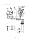
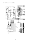
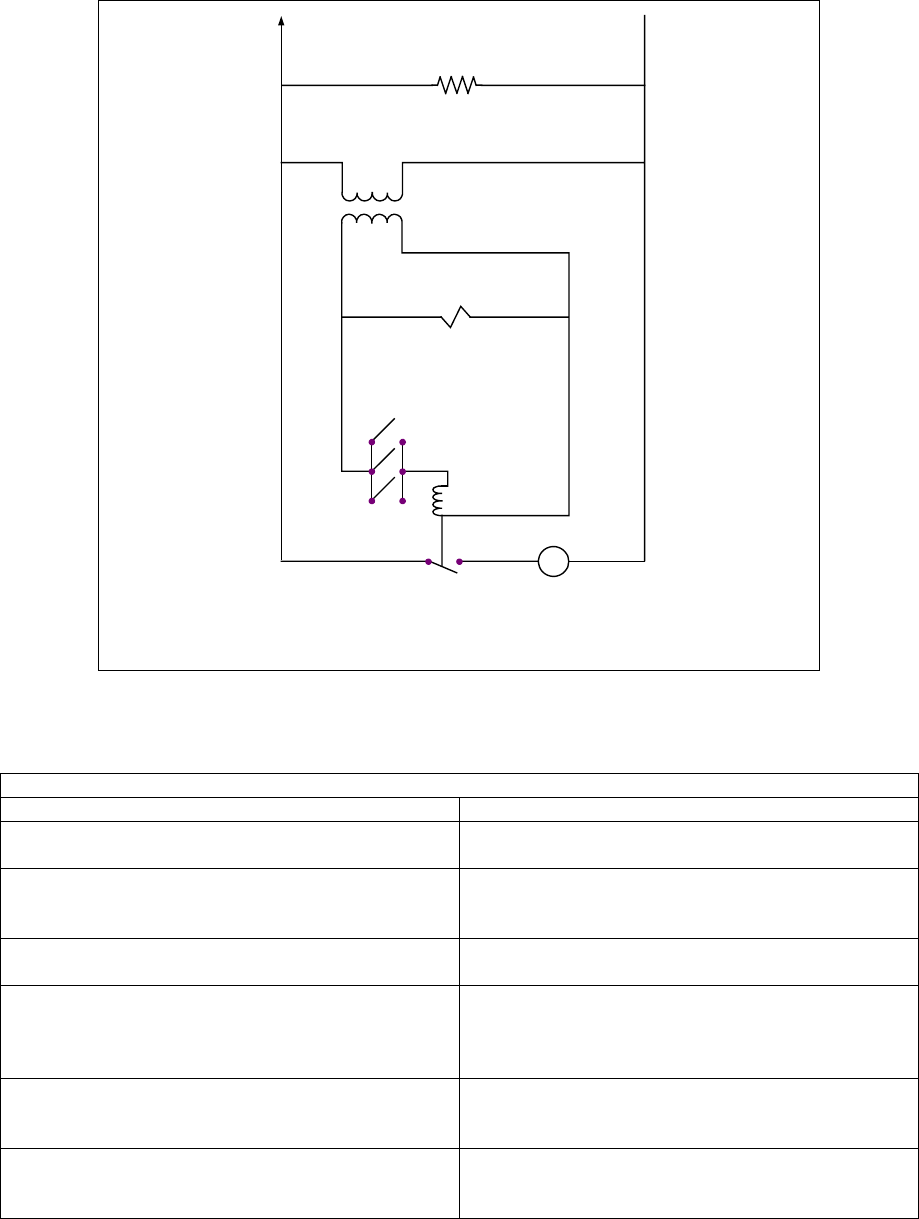
7-10: BUILT-IN FILTER SYSTEM SERVICE PROCEDURES (cont.)
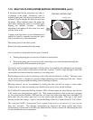
M
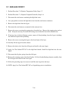
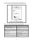
Pump Relay
Coil
Micro-switches
Pump Motor Switch
Pump Motor
Solenoids
(Redesigned Models Only)
24
VAC
Line
VAC
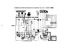
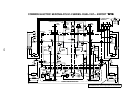
FootPrint III Wiring Diagram
All Heater Tapes (Original and
Redesigned Models)
(Heater Tapes have been removed from
return lines in Redesigned Models)
Operation of the redesigned FP-III system is the same as for the original design.
ORIGINAL VS REDESIGNED FP-III FILTRATION SYSTEM
Original System Redesigned System
Return lines and manifolds wrapped with silicone
strip heaters and aluminum tape.
No heater strips or aluminum tape on return
lines.
Filter base assembly connected to unit with a
black, heated return hose beneath the filter.
Non-heated Teflon hose with a swivel joint
connects the filter base assembly to the unit
above the filter.
Filter base assembly equipped with swivel
casters.
Filter base assembly has no casters.
Operator-removable filter base assembly. (Filter
base assembly stoplocks in cabinet can be
rotated to remove tray.)
Filter base assembly is not removable except by
a qualified service technician. (Filter base
assembly stoplocks fitted with a screw and nut to
prevent filter removal.)
Oil/shortening remains in return lines when filter
system is turned off.
Oil/shortening gravity-drains back to the filter pan
when filter system is turned off, leaving no oil or
shortening in return lines.
Return drain-manifolds are constructed with pipe
nipples, elbows and other plumbing components.
Return drain manifolds are one-piece with an in-
line solenoid valve to facilitate gravity drain-back
to filter pan.