


Chapter 3 Replacing Assemblies
To Remove A1 Motherboard Assembly
Assembly-Level Service Guide 3-9
3
To Remove A1 Motherboard Assembly
1 Remove the cover.
See the section titled “To Remove the Cover” in this chapter.
2 Remove the Power Supply Assembly.
See the section titled “To Remove A4 AC Power Supply Assembly” in this
chapter.
3 Remove the front bezel.
See the section titled “To Remove the Front Bezel” in this chapter.
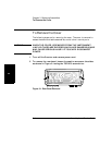
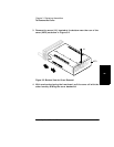
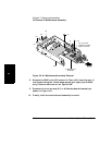
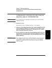
4 If the Counter contains Option 015/030/050/124 1.5/3.0/5.0/12.4 GHz
Channel, disconnect the optional channel’s flat-ribbon cable from
J7 on A1 Motherboard Assembly as shown in Figure 3-6.
5 If the Counter contains one of the optional high stability timebase
assemblies (Option 001, 010, 012), disconnect the flat-ribbon cable
from J6 of A1 Motherboard as shown in Figure 2-8A
(See Chapter 2, “Service.”).
6 If the Counter contains the Option 002 DC Power Input Assembly,
remove it.
See the section titled “To Remove A5 DC Power Input Assembly
(Option 002)” in this chapter.
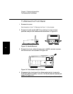
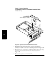
7 Remove the two hex screws (H4), shown in Figure 3-6, on the
rear-panel HP-IB connector using the 7-mm spin tight.