


Chapter 1 Performance Tests
Test 6: Peak Volts, Channel 1 (HP 53181A Only)
Assembly-Level Service Guide 1-69
1
Procedure
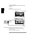
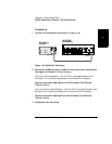
1 Connect the equipment as shown in Figure 1-16.
Figure 1-16. Peak Volts Test Setup
2 Set the HP 3325B to output a 2 MHz, 2 Vp-p sine wave, and connect
the signal to Channel 1 of the Counter.
The Counter should display
−
1.00 ±0.12V for the negative peak of the
sine wave. This reading is displayed on the left side of the display.
Record the actual readings in the Performance Test Record
(Test 6, Line a).
Also, the Counter should display +1.00 ±0.12V for the positive peak of the
sine wave. This reading is displayed on the right side of the display.
Record the actual readings in the Performance Test Record
(Test 6, Line b).
3 Disconnect the test setup.
HP 53181A
Counter
Channel 1
HP 3325B
Synthesizer
Output