


Chapter 3 Replacing Assemblies
To Remove A3 1.5/3.0/5.0/12.4 GHz Channel Assembly (Option
015/030/050/124)
Assembly-Level Service Guide 3-13
3
To Remove A3 1.5/3.0/5.0/12.4 GHz Channel
Assembly (Option 015/030/050/124)
NOTE
The 1.5 GHz Channel 2 Assembly is available only for the HP 53181A
Frequency Counter.
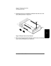
1 Remove the cover.
See the section titled “To Remove the Cover” in this chapter.
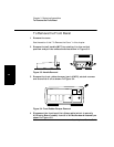
2 Using the 14-mm deep-socket spin tight, remove the BNC nut (H3)
from the optional Channel 3 (or Channel 2 for HP 53181A) input
connector (Options 015/030 only). For Option 050 or 124 remove
the knurled nut using a pair of pliers.
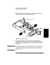
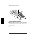
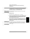
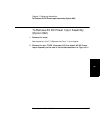
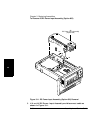
3 Pull W1, which is the optional channel assembly cable, out of the
Channel 3 (or 2) opening in the front panel assembly as shown in
Figure 3-8. For the Option 050 or 124, the connector is part of the
Option assembly.
CAUTION When reassembling A3 (Option 015/030) Assembly, ensure that cable W1
is not placed or folded on top of the input circuits of A1 Motherboard
Assembly or is tucked behind A3 as the Counter may start reading or
measuring noise.