


Chapter 8 HP 53181A Specifications
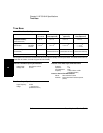
Instrument Inputs (Continued)
Assembly-Level Service Guide 8-3
8
3
Channel 2 is available as an option.
4
When ordered with optional rear terminals, the Channel 2 connector on the front panel for Options 015 or 030 will be removed. There is no
degradation in specifications for this input. Option 050 and Option 124 input connectors are available on the front panel only.
Instrument Inputs (Continued)
Channel 2 Input Specifications
3, 4
Channel 2 Input Characteristics
Frequency Range
Opt. 015 100 Mhz to 1.5 Ghz
Opt. 030 100 MHz to 3 GHz
Opt. 050 200MHz to 5 GHz
Opt. 124 200 MHz to 12.4 GHz
Power Range and Sensitivity (Sinusoid)
Option 015
100 MHz to 1.5 GHz: –27 dBm to +19 dBm
Option 030
100 MHz to 2.7 GHz: –27 dBm to +19 dBm
2.7 GHz to 3 GHz: –21 dBm to +13 dBm
Option 050
200MHz to 5 GHz: –23 dBm to +13 dBm
Option 124
200MHz to 12.4 GHz: –23 dBm to +13 dBm
Damage Level:
Option 015, 030 5 Vrms
Option 050, 124 +25 dBm
Impedance: 50 Ω
Coupling: AC
VSWR: < 2.5:1
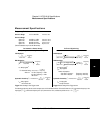
External Arm Input Specifications External Arm Input Characteristics
Signal Input Range:
TTL compatible
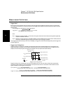
Timing Restrictions:
Pulse Width: > 50 ns
Transition Time: < 250 ns
Start-to-Stop Time: > 50 ns
Damage Level: 10 Vrms
Impedance: 1 kΩ
Input Capacitance: 17 pF
Start Slope: Positive or Negative
Stop Slope: Positive or Negative
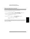
Notes:
External Arm available for all measurements except Peak Volts.
External Arm is referred to as External Gate for some
measurements.